Hybrid optical fiber amplifier, optical signal amplification method and optical communication system

A hybrid optical fiber and amplifier technology, applied in lasers, transmission systems, laser components, etc., can solve problems such as wavelength loss, difficulty in automatic gain control, and complex gain control of hybrid fiber amplifiers

Active Publication Date: 2020-09-22
GUANGXUN SCI & TECH WUHAN
View PDF8 Cites 9 Cited by
  • Summary
  • Abstract
  • Description
  • Claims
  • Application Information

AI Technical Summary

Problems solved by technology

[0003] In the current existing technical scheme, if the C+L-band is amplified, the C+L-band must be separated into two independent C-bands and L-bands, and then separately amplified and then passed through wavelength division multiplexing (WDM, Wavelength DivisionMultiplexing) method for multiplexing, so that there are always several wavelengths (3-5nm bandwidth) in the middle of the frequency band that are lost due to multiplexing
In the current technology, there are also hybrid amplifiers composed of distributed Raman fiber amplifiers and EDFA, but the operating wavelength of distributed RFA and EDFA is the same. This hybrid fiber amplifier mainly utilizes the characteristics of low noise index of distributed Raman fiber amplifiers , reduce the noise figure of the hybrid fiber amplifier, improve the optical signal-to-noise ratio (OSNR, Optical SignalNoise Ratio) of the system, instead of widening the channel bandwidth, due to the difficulty of automatic gain control of the distributed Raman fiber amplifier, the traditional hybrid fiber amplifier The gain control of the

Method used


Image

  • Hybrid optical fiber amplifier, optical signal amplification method and optical communication system
  • Hybrid optical fiber amplifier, optical signal amplification method and optical communication system
  • Hybrid optical fiber amplifier, optical signal amplification method and optical communication system

Examples


Embodiment Construction

[0031] The essence of the technical solutions of the embodiments of the present application will be explained in detail below in conjunction with the accompanying drawings.

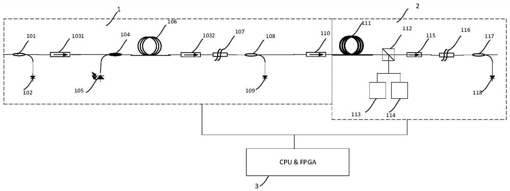
[0032] In the embodiment of this application, the lumped RFA can theoretically amplify the entire C+L-band, but because the C+L-band is relatively wide, multiple pump wavelengths are required to achieve flat gain, and multiple pump wavelengths are There will be interaction and influence in the highly nonlinear fiber, which brings great difficulties to the gain flat control of the lumped Raman amplifier; in addition, whether it is a lumped Raman fiber amplifier or a distributed Raman fiber amplifier, the Raman The Mann gain cannot be too large, otherwise it will cause strong multipath interference. Therefore, the gain of the lumped Raman amplifier is reduced by sharing most of the gain through the EDFA, thereby reducing the multipath interference of the amplifier and improving the performance of the fiber a...


PUM

PropertyMeasurementUnit
wavelengthaaaaaaaaaa

Abstract

The embodiment of the invention discloses a hybrid optical fiber amplifier, an optical signal amplification method and an optical communication system. The hybrid optical fiber amplifier comprises: anerbium-doped optical fiber amplifier which is used for amplifying optical signals of C and L wave bands in an optical path and filtering out parts, with gain exceeding a set threshold value, in the amplified optical signals of the C and L wave bands, so that the power of the optical signals of the C and L wave bands output to the rear end of the optical path is balanced in each channel; and a lumped Raman optical fiber amplifier, wherein the input end of the lumped Raman optical fiber amplifier is connected with the output end of the erbium-doped optical fiber amplifier through a high-nonlinearity optical fiber or a dispersion compensation optical fiber, and the lumped Raman optical fiber amplifier is used for amplifying the optical signals which are not amplified by the erbium-doped optical fiber amplifier in the output optical signals of the C waveband and the L waveband. The EDFA and Raman belong to lumped optical fiber amplifiers, the gain control can be realized through local input and output power detection, and the gain control is very convenient.

Description

technical field [0001] Embodiments of the present application relate to optical fiber communication technology, and in particular to a hybrid optical fiber amplifier supporting C+L frequency band amplification, an optical signal amplification method, and an optical communication system. Background technique [0002] In the field of optical communication, in order to make the communication system have a large enough capacity, the ultra-broadband fiber amplifier becomes one of the essential devices. Erbium-doped fiber amplifier (EDFA, Erbium-Doped Fiber Amplifier) ​​and Raman fiber amplifier (RFA, Raman Fiber Amplifier) ​​has been widely used in optical communication systems. With the gradual commercialization of single-channel 400G coherent communication systems, the channel spacing is getting larger and larger. The traditional 50GHz spacing can no longer meet the requirements of high-speed communication systems. Currently, based on dual The minimum channel spacing of carrier...

Claims


Application Information

Patent Timeline
Patent Type & Authority Applications(China)
IPC IPC(8): H04B10/291H04B10/293H01S3/067
CPCH01S3/06758H01S3/06766H01S3/0677H04B10/2916H04B10/293
Inventor 付成鹏卜勤练陶金涛侯梦军刘青乐孟辉余春平
Owner GUANGXUN SCI & TECH WUHAN
Why Eureka
Try Eureka