
Loop gain control system and method

A technology for controlling system and loop gain, applied in the field of communication, can solve the problem of inability to control the gain of downlink signal of MIMO system

Active Publication Date: 2017-10-20
COMBA TELECOM SYST CHINA LTD
View PDF7 Cites 3 Cited by
  • Summary
  • Abstract
  • Description
  • Claims
  • Application Information

AI Technical Summary

Problems solved by technology

[0003] Embodiments of the present invention provide a loop gain control system and method, which are used to solve the technical problem in the prior art that the gain of the downlink signal in the MIMO system cannot be controlled

Method used


Image

  • Loop gain control system and method
  • Loop gain control system and method
  • Loop gain control system and method

Examples


Embodiment 1

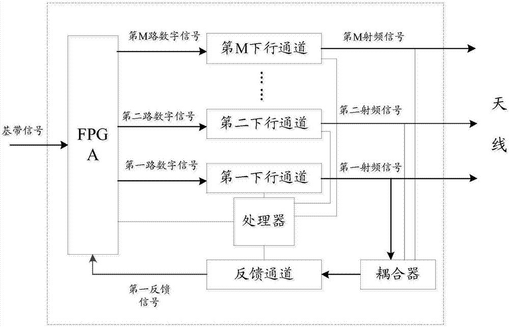
[0037] Embodiment 1 of the present invention provides a loop gain control system, including: a Field-Programmable Gate Array (Field-Programmable Gate Array, FPGA) chip, a feedback channel, a processor, and M downlink channels, where M is not less than 2 positive integer.

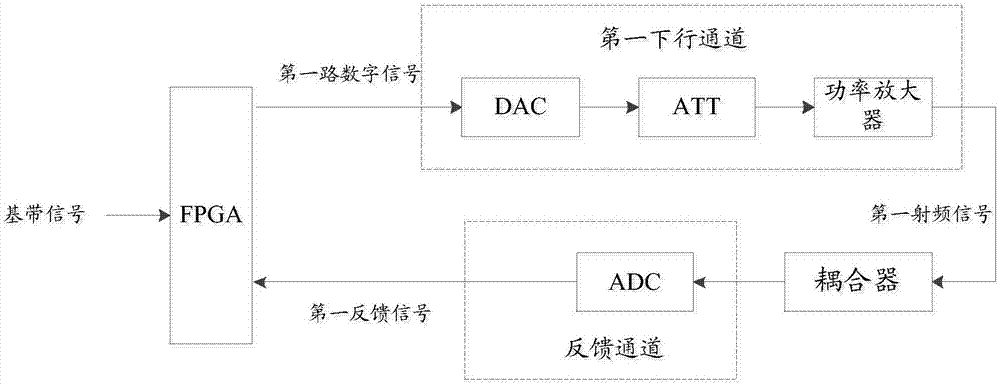
[0038] In the embodiment of the present invention, the downlink channel refers to all physical elements between the signal output end of the FPGA chip in the radio remote unit (Radio Remote Unit, RRU) and the signal input end of the antenna. The physical channel of the signal of the antenna, the feedback channel is a physical channel for transmitting the signal fed back from the antenna formed by all the physical elements between the signal input end of the antenna and the feedback signal input end of the FPGA.

[0039] refer to figure 1 , the internal structure of the system is: the processor is connected to the FPGA, the feedback channel, and M downlink channels respectively; the first input end of the FP...

Embodiment 2

[0094] Embodiment 2 of the present invention provides a downlink channel gain control method, the method is applied to a multiple-input multiple-output MIMO system, and the MIMO system includes an FPGA, a feedback channel, a processor, and M downlink channels, where M is not less than 2 positive integer; see Figure 4 , the method includes:

[0095] Step 11, process the baseband signal through the FPGA to form M digital signals, and respectively perform gain amplification on the M digital signals, and output the M digital signals after gain amplification to the M downlink channel;

[0096] Step 12, receiving the first digital signal among the M digital signals through the first downlink channel among the M downlink channels, performing digital-to-analog conversion and gain amplification on the first digital signal to form a second A radio frequency signal, the first radio frequency signal is used by the antenna to transmit a downlink signal, the first downlink channel is any...


PUM


Abstract

The embodiment of the invention provides a loop gain control system and method used for performing gain control on a downlink signal in an MIMO system. The system comprises a field programmable gate array FPGA, a feedback channel, a processor and M downlink channels, wherein M is a positive integer not smaller than 2; and the gain of the loop formed by the FPGA, any one of the M downlink channels and the feedback channel is controlled by the processor, and thus the gain control of the downlink signal in the MIMO system is realized.

Description

technical field [0001] The invention relates to the field of communication technology, in particular to a loop gain control system and method. Background technique [0002] Multiple-Input Multiple-Out-put (MIMO) technology is one of the core technologies of mobile communication, and the MIMO system has great advantages in terms of network speed and quality. During the research on the MIMO system, it is found that the total power dynamic range of the downlink signal output by the existing MIMO system is often critical or even exceeds the requirements of the 3GPP 3rd Generation Partnership Project (3rd Generation Partnership Project, 3GPP) agreement, so it is necessary to The gain of the downlink signal of the MIMO system is controlled. However, since the downlink signal of the MIMO system is output through multiple different output channels, it is necessary to individually perform gain control on each output channel, and the prior art cannot meet the requirements of the MIMO...

Claims


Application Information

Patent Timeline
Patent Type & Authority Applications(China)
IPC IPC(8): H04B7/0426H04B7/0417H04W52/08H04W52/14H04W52/18H04W52/42
CPCH04B7/0417H04B7/0426H04W52/08H04W52/143H04W52/18H04W52/42Y02D30/70
Inventor 高永振黄鹏飞雷文明葛卫敏
Owner COMBA TELECOM SYST CHINA LTD
Learn More