A fastening ring for cable installation and fixing of power transmission equipment and its implementation method
A technology for cable installation and power transmission, which is applied in the direction of cable installation, cable installation devices, electrical components, etc. It can solve the problems of complicated installation procedures, inability to ensure stable installation of cables, and inability to deal with wear and tear on the outer wall of cables to achieve convenient installation procedures. Effect
- Summary
- Abstract
- Description
- Claims
- Application Information
AI Technical Summary
Problems solved by technology
Method used
Image
Examples
Embodiment 1
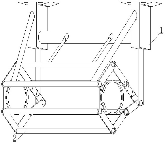
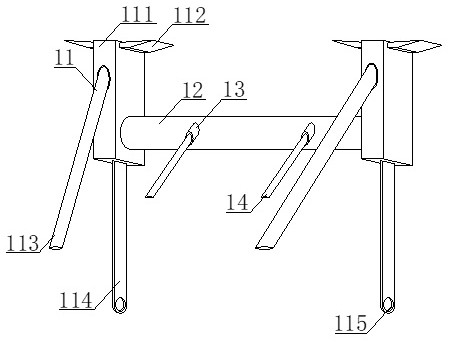
[0033] see figure 1 , figure 2 , image 3 , Figure 4 , Figure 5 and Figure 6 , a fastening ring for cable installation and fixation of power transmission equipment, including a mounting bracket 1 and a fastening mechanism 2, the mounting bracket 1 includes a support top frame 11, a lateral support link 12, a front installation support shell 13 and a front movable link 14. The support top frames 11 are movably connected by the horizontal support link 12. The support top frame 11 includes the installation vertical box 111, the connecting ear block 112, the connecting oblique rod 113, the telescopic vertical rod 114 and the side mounting hole 115. Both sides of the top of the box 111 are equipped with connecting double-ear blocks 112, and the installation vertical box 111 is provided with two groups. It is movably connected with the wall, and the device can be placed on the top of the end surface at different angles by using the movable screw rod, so that the device has ...
Embodiment 2
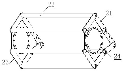
[0035] see Figure 7 and Figure 8 , the first movable mechanism 21 comprises an upper movable mechanism 211, an adjustment base rod 212, a first connecting member 213, a series rod 214, a second connecting key 215, a lower movable mechanism 216 and a connection belt 217, and the right lower end of the upper movable mechanism 211 Adjustment base bar 212 is installed, and upper movable mechanism 211 includes left positioning bar 2111, serial part 2112 and right positioning bar 2113, and left positioning bar 2111 is connected with right positioning bar 2113 through serial part 2112, and adjusting base bar 212 includes lower embedded shell 2121, the series hole 2122, the inner cavity shell 2123, the movable inner block bar 2124 and the upper inlay shell 2125, the bottom end of the lower inlay shell 2121 is provided with a series hole 2122, and the upper end of the lower inlay shell 2121 is equipped with an upper connection Inner chamber shell 2123, the inner cavity of connecting...
Embodiment approach
[0036] In order to better demonstrate the implementation method of the fastening ring for installing and fixing the cable of the power transmission equipment, this embodiment now proposes the implementation method of the fastening ring for installing and fixing the cable of the power transmission equipment, including the following steps:
[0037] S1: Place the overall device in the position where the cable needs to be installed, and connect the inner cavity of the double ear block 112 through the movable screw, so that it can be flexibly connected with the wall;
[0038] S2: After determining the position, place the cable in the inner cavity of the ring body 241, which is a semi-circular member. The connecting piece 213 is movably connected, thereby using the first connecting piece 213 as the fulcrum to adjust the base rod 212 and the series rod 214 for adjustment, the adjustment base rod 212 shrinks and the right end runs counterclockwise upward, and the right end of the serie...
PUM
 Abstract
Description
Claims
Application Information
 - Generate Ideas
- Intellectual Property
- Life Sciences
- Materials
- Tech Scout
- Unparalleled Data Quality
- Higher Quality Content
- 60% Fewer Hallucinations
Browse by: Latest US Patents, China's latest patents, Technical Efficacy Thesaurus, Application Domain, Technology Topic, Popular Technical Reports.
© 2025 PatSnap. All rights reserved.Legal|Privacy policy|Modern Slavery Act Transparency Statement|Sitemap|About US| Contact US: help@patsnap.com


