
A ventilation device for logistics in underground pipe gallery

An underground pipe gallery and ventilation device technology, which is applied to underwater structures, applications, household heating and other directions, can solve the problems of inability to purify the air, affect the air environment of the underground pipe gallery, low ventilation efficiency, etc. The effect of environmental comfort, improving purification efficiency and improving ventilation rate

Active Publication Date: 2021-07-02
JIAOZUO UNIV
View PDF0 Cites 0 Cited by
  • Summary
  • Abstract
  • Description
  • Claims
  • Application Information

AI Technical Summary

Problems solved by technology

[0003] Due to special environmental reasons, the development of the underground comprehensive pipe gallery needs to be ventilated to ensure that there is sufficient fresh air in the underground comprehensive pipe gallery; the existing ventilation system can only carry out ventilation, and only natural Ventilation, the ventilation efficiency is low; and it is impossible to purify the air entering the underground pipe gallery, so that dust or germs enter the underground pipe gallery, affecting the air environment of the underground pipe gallery

Method used


Image

  • A ventilation device for logistics in underground pipe gallery
  • A ventilation device for logistics in underground pipe gallery
  • A ventilation device for logistics in underground pipe gallery

Examples


Embodiment 1

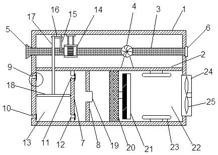
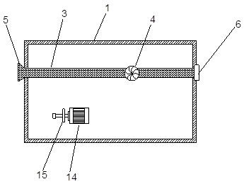
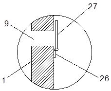
[0039] Such as Figure 1-5As shown, a ventilation device for the flow of underground pipe corridors; it includes a housing 1; a first partition 2 is provided inside the housing 1, and an exhaust pipe 3 is provided above the first partition 2 , the exhaust pipe 3 is connected with an exhaust fan 4, and the exhaust is exhausted through the exhaust fan 4; one end of the exhaust pipe 3 is connected with an exhaust hood 5, and the exhaust hood 5 is inlaid and connected with the housing 1 The other end of the exhaust pipe 3 is connected with an air intake cover 6, and the air intake cover 6 is inlaid and connected with the housing 1; a second partition 7 is provided below the first partition 2, and the second partition 7 A closed air intake cavity 13 is formed on one side close to the housing 1; a third partition 8 is provided on the other side of the second partition 7, and a vent 19 is opened in the center of the third partition 8; One side of the three partitions 8 away from the...

Embodiment 2

[0044] A ventilation device for the flow of underground pipe corridors; including a housing 1; the housing 1 is provided with a first partition 2 inside, and an exhaust pipe 3 is provided above the first partition 2, and the Exhaust pipe 3 is connected with exhaust blower 4, exhausts through exhaust blower 4; One end of described exhaust pipe 3 is connected with exhaust hood 5, and described exhaust hood 5 is inlay-connected with housing 1; Exhaust The other end of the pipe 3 is connected with an air intake cover 6, which is inlaid with the casing 1; a second partition 7 is provided below the first partition 2, and the second partition 7 is close to the casing One side of 1 forms a closed air intake cavity 13; the other side of the second partition 7 is provided with a third partition 8, and the center of the third partition 8 is provided with a vent 19; the third partition 8 A first filter screen 20 is provided on the side away from the second partition 7, the other side of t...

Embodiment 3

[0050] On the basis of Embodiment 1, the first filter screen 20 is a HEPA high-efficiency filter screen, which can filter a large amount of particulate pollutants contained in the natural air, and the filter diameter is 0.3 μm; several macromolecules.

[0051] In order to ensure the air quality in the underground pipe gallery, the fresh air volume V of the ventilation device and the carbon dioxide concentration C in the underground pipe gallery 1 and the carbon dioxide content in the fresh air, and the release amount of carbon dioxide n inhaled by personnel satisfy the following relationship:

[0052] V=α·(n / (C 1 -C 2 ));

[0053] In the above formula, α is the relationship coefficient, the value range is 0.569-3.323; V unit m 3 / h; C 1 、C 2 , The unit of n is ppm.

[0054] In order to ensure the air humidity and reasonable temperature in the underground pipe gallery, the temperature of the underground pipe gallery is adjusted through this device, and the heat exchange ...


PUM


Abstract

The invention discloses a ventilating device used for logistics in an underground pipe corridor; it includes a casing; a first partition is arranged inside the casing, and an exhaust pipe is arranged above the first partition. The trachea is connected with an exhaust fan, and exhaust is carried out through the exhaust fan; a second partition is provided under the first partition, and a closed air intake cavity is formed on the side of the second partition near the housing; the second The other side of the partition is provided with a third partition, and the center of the third partition is provided with an air vent; the side of the third partition away from the second partition is provided with a first filter screen, and the first filter is provided on the side of the third partition. The other side of a filter screen is connected with a filter body, and the other side of the filter body is provided with a sterilizing cavity, and the side of the sterilizing cavity away from the filter body is provided with an air inlet, and the air inlet is inlaid with the shell Connection; there is an exhaust fan inside the air inlet; the ventilation efficiency is high, and the air in the underground pipe gallery is purified to improve the air quality in the underground pipe gallery and ensure a healthy breathing environment.

Description

technical field [0001] The invention belongs to the field of ventilation equipment for underground pipe galleries, in particular to a ventilation device for logistics in underground pipe galleries. Background technique [0002] The underground comprehensive pipe gallery is a public tunnel built underground in the city for the centralized laying of municipal pipelines such as electricity, communications, radio and television, and water supply; the underground logistics system is an innovative logistics model. The underground logistics system not only has fast, It has the advantages of high accuracy, and is an important and effective way to solve urban traffic congestion, reduce environmental pollution, and improve the accessibility and quality of urban cargo transportation; the underground logistics system can meet the development model of circular economy and meet the development requirements of a resource-saving society. It is a necessary choice for the sustainable developm...

Claims


Application Information

Patent Timeline
Patent Type & Authority Patents(China)
IPC IPC(8): F24F3/16F24F7/003F24F7/007F24F8/108F24F11/32F24F11/64F24F11/74F24F11/88F24F13/28E02D29/045F24F110/10F24F110/40F24F110/70
CPCE02D29/10F24F3/16F24F7/007F24F13/28F24F11/32F24F11/64F24F11/74F24F11/88F24F2110/10F24F2110/40F24F2110/70Y02B30/70
Inventor 周冰王海花曾坤蓉王晟吴珅珅林邓伟
Owner JIAOZUO UNIV
Learn More