Fallen medical instrument pickup device for emergency department operating room
A technology of medical equipment, operating room, applied in the field of medical equipment picker
- Summary
- Abstract
- Description
- Claims
- Application Information
AI Technical Summary
Problems solved by technology
Method used
Image

Examples
Embodiment 1
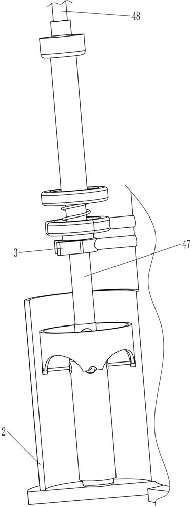
[0025] A kind of pick-up device for falling medical instruments in emergency department operating room, such as figure 1 , figure 2 and Figure 4 As shown, it includes a collection barrel 1, a placement frame 2, an arc snap ring 3, a magnetic attraction mechanism 4 and a release mechanism 5. The lower part of the left outer wall of the collection barrel 1 is connected with a placement frame 2, and the collection barrel 1 above the placement frame 2 The outer wall is connected with an arc-shaped snap ring 3 , and the placement frame 2 is provided with a magnetic attraction mechanism 4 , and a release mechanism 5 is connected to the magnetic attraction mechanism 4 .
[0026] The magnetic suction mechanism 4 includes a mounting tube 41, a guide sleeve 42, a guide rod 43, a magnetic suction head 44, a first spring 45, a connecting rod 46, a telescopic tube 47 and a grip bar 48, and a telescopic tube is placed in the arc snap ring 3. 47, the telescopic tube 47 is slidably connec...
Embodiment 2
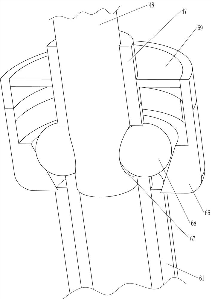
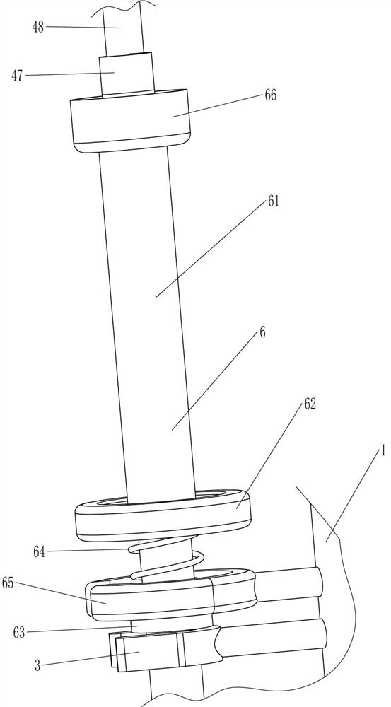
[0030] On the basis of Example 1, such as image 3 and Figure 5 As shown, it also includes a telescopic unlocking mechanism 6, and the telescopic unlocking mechanism 6 includes a slide tube 61, an iron plate 62, a fixed ring 63, a third spring 64, an arc magnet 65, an oblique sleeve 66, a ball 68 and a circular stop Plate 69, the outer wall of collection barrel 1 on the upper side of arc snap ring 3 is fixedly connected with arc magnet 65, the upper outer wall of telescopic tube 47 is slidably connected with slide tube 61, and the bottom end of slide tube 61 is connected with iron plate 62, iron Disk 62 is positioned at the upper side of arc magnet 65, and the outer wall of telescoping tube 47 of arc magnet 65 lower side is fixedly connected with fixed ring 63, is connected with the 3rd spring 64 between the top of fixed ring 63 and the bottom of iron plate 62, slides The top of the tube 61 is connected with a slanted sleeve 66, and the telescopic tube 47 on the upper side o...
Embodiment 3
[0033] On the basis of Example 2, such as figure 1 As shown, it also includes a pocket fixing mechanism 7, the pocket fixing mechanism 7 includes a placement ring 71 and a pressure ring 72, the upper outer wall of the collection barrel 1 is fixedly connected with the placement ring 71, and the outer wall of the collection barrel 1 on the upper side of the placement ring 71 The sliding connection has a pressure ring 72 .
[0034] When the aseptic bag is to be placed on the collection barrel 1, first the pressure ring 72 is removed from the collection barrel 1, then the aseptic bag is placed on the collection barrel 1, and then the pressure ring 72 is put back on the collection barrel 1 , and make the pressure ring 72 close to the placement ring 71, so that the head end of the aseptic bag can be fixed, and the aseptic bag can be kept stretched, so that the surgical tool can be conveniently dropped into the aseptic bag.
[0035] Such as figure 1 As shown, an anti-movement mecha...
PUM
| Property | Measurement | Unit |
|---|---|---|
| Height | aaaaa | aaaaa |
Abstract
Description
Claims
Application Information
 - R&D
- Intellectual Property
- Life Sciences
- Materials
- Tech Scout
- Unparalleled Data Quality
- Higher Quality Content
- 60% Fewer Hallucinations
Browse by: Latest US Patents, China's latest patents, Technical Efficacy Thesaurus, Application Domain, Technology Topic, Popular Technical Reports.
© 2025 PatSnap. All rights reserved.Legal|Privacy policy|Modern Slavery Act Transparency Statement|Sitemap|About US| Contact US: help@patsnap.com