
Display panel and display device

A technology of display panel and display area, applied in the direction of identification devices, instruments, etc., can solve the problems of long wiring distance, insufficient wiring space, and large impedance, and achieve the effect of shortening the wire distance and expanding the wiring space.

Inactive Publication Date: 2020-09-18
WUHAN CHINA STAR OPTOELECTRONICS TECH CO LTD
View PDF11 Cites 3 Cited by
  • Summary
  • Abstract
  • Description
  • Claims
  • Application Information

AI Technical Summary

Problems solved by technology

[0005] The purpose of the present invention is to provide a display panel and a display device, so as to solve the technical problems of the existing display panel wiring area to the driver chip, the wiring distance is too long, the impedance becomes larger, and the wiring space is insufficient

Method used


Image

  • Display panel and display device
  • Display panel and display device
  • Display panel and display device

Examples


Embodiment Construction

[0035] The technical solutions in the embodiments of the present application will be clearly and completely described below in conjunction with the drawings in the embodiments of the present application. Apparently, the described embodiments are only some of the embodiments of this application, not all of them. Based on the embodiments in this application, all other embodiments obtained by those skilled in the art without making creative efforts belong to the scope of protection of this application.

[0036] In the description of the present application, it should be understood that the terms "first" and "second" are used for description purposes only, and cannot be interpreted as indicating or implying relative importance or implicitly indicating the quantity of indicated technical features. Thus, a feature defined as "first" or "second" may explicitly or implicitly include one or more of said features. In the description of the present application, "plurality" means two or ...


PUM


Abstract

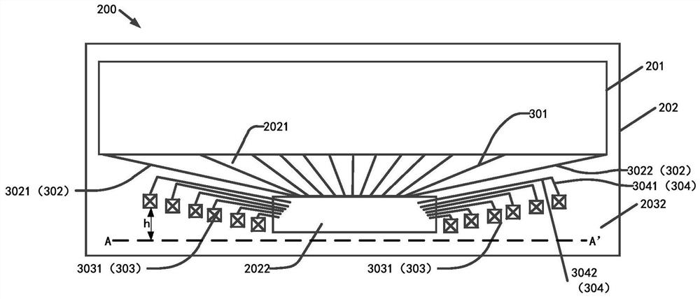
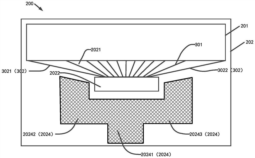
The invention discloses a display panel and a display device. The display panel is provided with a display area and a non-display area surrounding the display area, the display panel further comprisesa fan-out area and a driving chip, a datum line is preset below the driving chip, the datum line is parallel to one side edge, connected with the fan-out area, of the display area, and the side, awayfrom the fan-out area, of the non-display area is further provided with flat cable areas which are distributed on the two sides of the driving chip. The display panel further comprises a plurality ofbonding pads and wires. The bonding pads are distributed in the flat cable area and located on the two sides of the driving chip, each bonding pad is connected to the driving chip through a wire, andon each side of the driving chip, the heights of the bonding pads on the datum line are gradually increased in the direction from the position close to the driving chip to the position away from thedriving chip.

Description

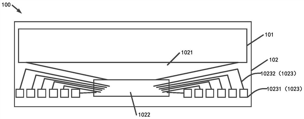
technical field [0001] The present application relates to the field of display technology, in particular to a display panel and a display device. Background technique [0002] With the technical development of full-screen displays, the screen-to-body ratio of the current display screen is continuously increasing, and the lower border of the display screen is also getting smaller and smaller. [0003] Such as figure 1 As shown, the existing display panel 100 includes a display area 101 and a non-display area 102 surrounding the display area 101. In the non-display area 102, a fan-out area 1021, a driver chip 1022, and a wiring area 1023 (Flexible Printed Circuit Board, FPC ). [0004] The wiring area 1023 is distributed on both sides of the driving chip 1022 , and the wiring area 1023 includes a pad 10231 and a first wiring 10232 . The central connection lines of the plurality of pads 1023 are on the same horizontal line, and the first wiring 10232 is used to connect the p...

Claims


Application Information

Patent Timeline
Patent Type & Authority Applications(China)
IPC IPC(8): G09F9/00
CPCG09F9/00
Inventor 卢延涛刘广辉王超
Owner WUHAN CHINA STAR OPTOELECTRONICS TECH CO LTD
Learn More