
Method and device for oscillation identification of power system

A power system and oscillation identification technology, applied in the field of power system, can solve the problems of oscillation mode change, inability to identify the phase, difficult to identify the accuracy, etc.

Active Publication Date: 2021-07-23
BEIJING JIAOTONG UNIV
View PDF10 Cites 0 Cited by
  • Summary
  • Abstract
  • Description
  • Claims
  • Application Information

AI Technical Summary

Problems solved by technology

However, since the synchronized phasor data only contains the fundamental wave phasor corresponding to the fundamental frequency, when oscillation occurs in the power system, the oscillation component only appears in the fundamental wave phasor due to spectrum leakage, so although the synchronized phasor data contains Oscillation information, but the oscillation component of the power system cannot be directly calculated from the frequency spectrum analysis results of the synchronized phasor data
[0004] At present, the main technical problems of existing power system oscillation identification methods based on synchrophasors are as follows: On the one hand, when performing frequency spectrum analysis on synchrophasor data, large The real-time performance of oscillation identification is poor. For example, to ensure the spectral resolution of 0.1 Hz, a data window with a length of at least 10 seconds is required; furthermore, the poor real-time performance of oscillation identification will lead to poor identification results, because the data The larger the window length, the more likely the oscillation mode of the power system will change
On the other hand, the existing power system oscillation identification methods based on synchronized phasors can only identify the frequency and amplitude, but not the phase, especially when the oscillation process contains positive or negative damping ratio, that is, the attenuation factor , it is more difficult to identify the influence of the attenuation factor and further seriously affect the accuracy of identification

Method used


Image

  • Method and device for oscillation identification of power system
  • Method and device for oscillation identification of power system
  • Method and device for oscillation identification of power system

Examples


Embodiment Construction

[0028] Embodiments of the present invention are described in detail below, examples of which are shown in the drawings, wherein the same or similar reference numerals denote the same or similar elements or elements having the same or similar functions throughout. The embodiments described below by referring to the figures are exemplary only for explaining the present invention and should not be construed as limiting the present invention.

[0029] In order to facilitate the understanding of the embodiments of the present invention, several specific embodiments will be taken as examples for further explanation below in conjunction with the accompanying drawings, and each embodiment does not constitute a limitation to the embodiments of the present invention.

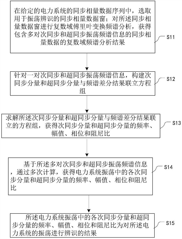
[0030] Such as figure 1 As shown, it is a method of oscillation identification of a power system according to the present invention, including:

[0031] Step 11: Select a synchronized phasor data window for oscillation i...


PUM


Abstract

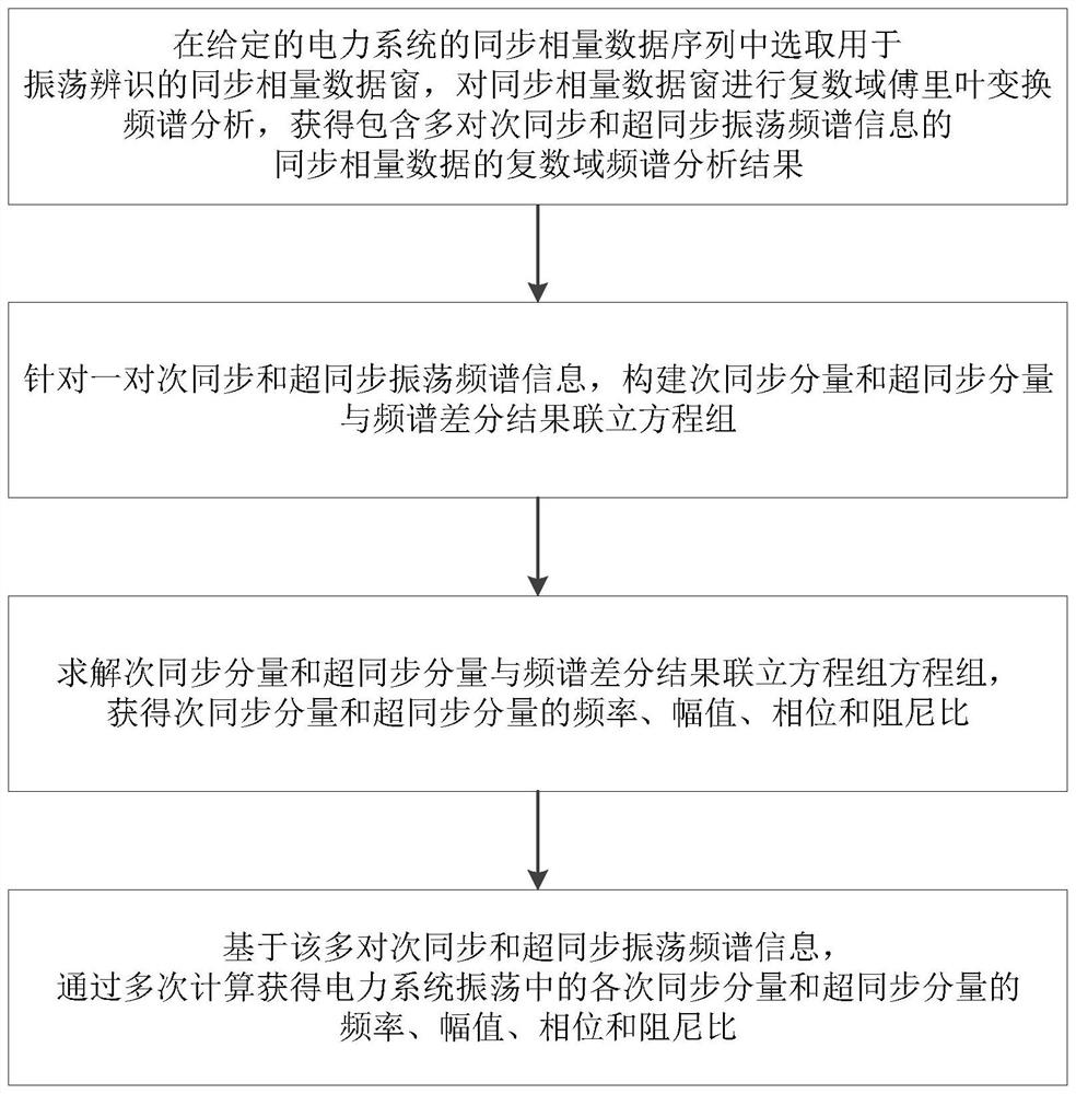
Embodiments of the present invention provide a method and device for oscillation identification of a power system. The method includes: selecting a synchronized phasor data window for oscillation identification in a given synchronized phasor data sequence of a power system; performing complex domain Fourier transform spectrum analysis on the synchronized phasor data window, Obtain the complex domain spectrum analysis results of synchrophasor data containing multiple pairs of subsynchronous and supersynchronous oscillation spectrum information; for a pair of subsynchronous and supersynchronous oscillation spectrum information, construct a simultaneous cube of subsynchronous components, supersynchronous components and spectral difference results Process group; Solving the equation system of the subsynchronous component and the supersynchronous component and the spectrum difference result simultaneously, obtain the frequency, amplitude, phase and damping ratio of the subsynchronous component and the supersynchronous component; Based on the multiple pairs of subsynchronous and Supersynchronous oscillation spectrum information, through multiple calculations, the frequency, amplitude, phase and damping ratio of each synchronous component and supersynchronous component in the power system oscillation are obtained.

Description

technical field [0001] The invention relates to the field of electric power systems, in particular to a method and device for identifying oscillations in electric power systems. Background technique [0002] When the power system is disturbed or the operating state changes during normal operation, various oscillations may occur, and the oscillations often last for more than ten seconds or even several minutes. The operating state of the power system is closely related to the oscillation characteristics it generates. The long transmission lines of cross-regional interconnection grids are prone to power oscillations under heavy load conditions, and large-scale wind power generation dominated by a large number of doubly-fed wind turbines and transmission channel series compensators are prone to occur under the condition that only subsynchronous components are involved. Subsynchronous oscillation, large-scale wind power generation dominated by a large number of permanent magnet...

Claims


Application Information

Patent Timeline
Patent Type & Authority Patents(China)
IPC IPC(8): G01R23/16G01R23/02G01R23/06
CPCG01R23/02G01R23/06G01R23/16
Inventor 张放刘军王小君和敬涵许寅吴翔宇
Owner BEIJING JIAOTONG UNIV
Learn More