Closed explosion-proof tank

An explosion-proof tank and closed technology, which is applied in the direction of blasting, construction, building fastening devices, etc., can solve the problems of weak locking structure, large safety hazards of open explosion-proof tanks, and large safety hazards, and achieve excellent anti-explosion performance , the effect of reducing the lethal effect

Pending Publication Date: 2020-09-18
梁荣
View PDF9 Cites 0 Cited by
  • Summary
  • Abstract
  • Description
  • Claims
  • Application Information

AI Technical Summary

Problems solved by technology

[0004] Aiming at the problems that the existing open explosion-proof tanks have large potential safety hazards, and the locking structure of the tank cover (tank door) of the closed explosion-proof tank is weak, and the potential safety hazards are large, the invention pr

Method used


Image

  • Closed explosion-proof tank
  • Closed explosion-proof tank
  • Closed explosion-proof tank

Examples


Embodiment 1

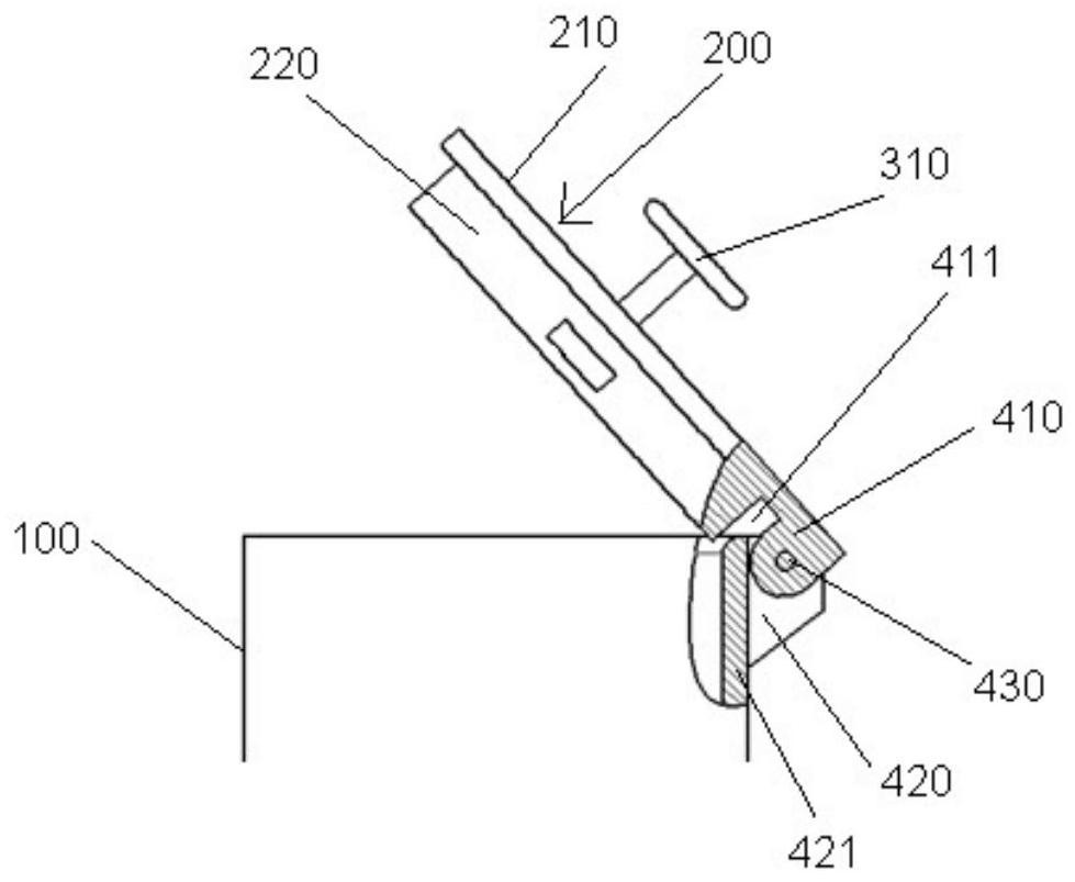
[0037] Such as Figure 1-4 As shown, a closed explosion-proof tank of this embodiment includes a tank body 100, a tank cover 200 and a locking mechanism. One side of the can cover 200 has a connecting plate 410, and the corresponding can body 100 has a connecting block 420, and the two are connected by a pin 430 to form a hinge structure. Through this hinge structure, the can body 100 and the can cover 200 are connected in rotation. That is, the can lid 200 rotates relative to the can body 100 around the pin 430 to realize the opening or closing of the can lid 200. The can lid 200 is integrally formed by a lid 210 and a lid 220. The diameter of the can 100 is between the diameter of the lid 210 and the diameter of the lid 220. In the closed state, the lid 210 is located above the can 100, and the lid 220 is embedded The inside of the tank body 100 fits with the inner wall of the tank body 100.

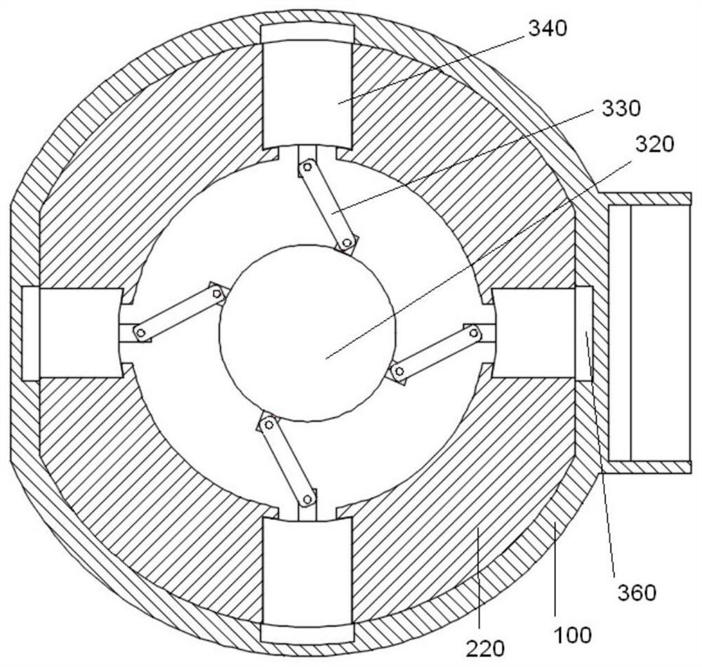
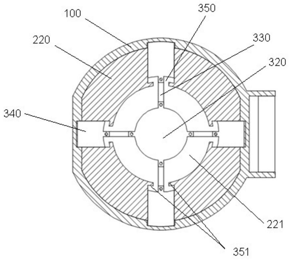
[0038] There is a cavity 221 in the middle of the cover 220, four pin holes 350 ar...

Embodiment 2

[0049] This embodiment is different from the first embodiment in that the socket and the locking pin are the socket 360 in this embodiment is through. Such as Figure 5 As shown, the insertion hole 360 ​​penetrates the side wall of the can body 100, and when the locking pin 340 is completely inserted into the insertion hole 360, it protrudes out of the side wall of the can body 100, and the locking pin 340 is stuck on the entire side of the can body 100. On the wall, in the locked state, the tank cover 200 and the tank body 100 are more closely combined, so that the closed explosion-proof tank has a stronger ability to suppress and weaken the shock wave generated at the moment of explosion.


PUM

PropertyMeasurementUnit
Thicknessaaaaaaaaaa
Thicknessaaaaaaaaaa

Abstract

The invention relates to a closed explosion-proof tank. The tank comprises a tank cover, a tank body, a tank bottom and a locking mechanism, wherein the tank cover is vertically and rotatably connected with the tank body through a hinge pin, the interior of the tank cover and the side wall of the tank body are integrally an soft and hard superposed, and staggered ordered weak explosion structure,an irregular explosion venting small hole is formed in the tank cover, the locking mechanism comprises a rotating handle, a rotating shaft, a crank, a lock pin, a pin hole and an inserting hole, wherein the crank is located inside the tank cover, the center of the crank is connected with the rotating handle through the rotating shaft vertically penetrating through the tank cover, the edge of the crank is correspondingly connected with a locking pin located in the pin hole through a connecting rod, the pin hole is located inside the tank cover, the outer side of the pin hole passes through theside wall of the tank cover, the pin hole is opposite to the inserting hole located inside the side wall of the tank body when the tank cover is closed to form a sliding rail of the locking pin, the rotating handle is rotated to drive the locking pin to slide along the sliding rail to insert or exit the inserting hole so as to lock or unlock the tank cover. The closed explosion-proof tank has theadvantages of tank and cover integrity, and quick, convenient and safe explosion venting.

Description

Technical field [0001] The invention relates to a closed explosion-proof tank, which belongs to the field of security inspection, explosion-proof and explosion discharge. Background technique [0002] The explosion-proof tank is mainly used for temporary storage and transfer of suspicious explosives. If the suspicious object explodes during the transfer and temporary storage, it can effectively protect the surrounding personnel and objects from damage. It is a necessary equipment for security inspection (emission) explosion prevention by security inspection departments such as public security, armed police, civil aviation, railways, ports, customs, and competition venues. [0003] Explosion-proof tanks include open and closed. The scope of use of open explosion-proof tanks is limited, and they are mostly used outdoors and in open areas. There are great safety hazards for indoor use, such as secondary damage results; closed explosion-proof The tank includes the tank body, the tank ...

Claims


Application Information

Patent Timeline
IPC IPC(8): F42D5/04F42D5/045E05C9/06E05C9/16
CPCF42D5/04F42D5/045E05C9/063E05C9/16
Inventor 赵宁李力梁荣
Owner 梁荣
Why Eureka
Try Eureka