
H-shaped steel column and base assembled joint and construction method

An H-beam, prefabricated technology, applied in construction, building structure, etc., can solve the problems of low construction efficiency, low bearing strength, small welding contact surface, etc., to improve construction efficiency, convenient positioning and installation, high bearing strength Effect

Inactive Publication Date: 2020-09-18
安徽跨宇钢结构网架工程有限公司
View PDF0 Cites 5 Cited by
  • Summary
  • Abstract
  • Description
  • Claims
  • Application Information

AI Technical Summary

Problems solved by technology

[0002] In multi-story and high-rise steel structures, H-shaped steel beams and H-shaped steel columns are used as the main load-bearing components, especially the connection stability of H-shaped steel columns determines the overall strength of the steel structure. Most of the existing steel structure columns and bases are Through welding connection, the welding contact surface is small, the bearing strength is low, and the process requirements are high, and the construction is more complicated. In addition, the connection between the H-shaped steel column and the base requires precise positioning of the H-shaped steel column, and the H-shaped steel column is long and difficult to move. , cumbersome positioning and low construction efficiency

Method used


Image

  • H-shaped steel column and base assembled joint and construction method
  • H-shaped steel column and base assembled joint and construction method
  • H-shaped steel column and base assembled joint and construction method

Examples


Embodiment Construction

[0025] In order to make the technical means, creative features, goals and effects achieved by the present invention easy to understand, the present invention will be further described below in conjunction with specific embodiments.

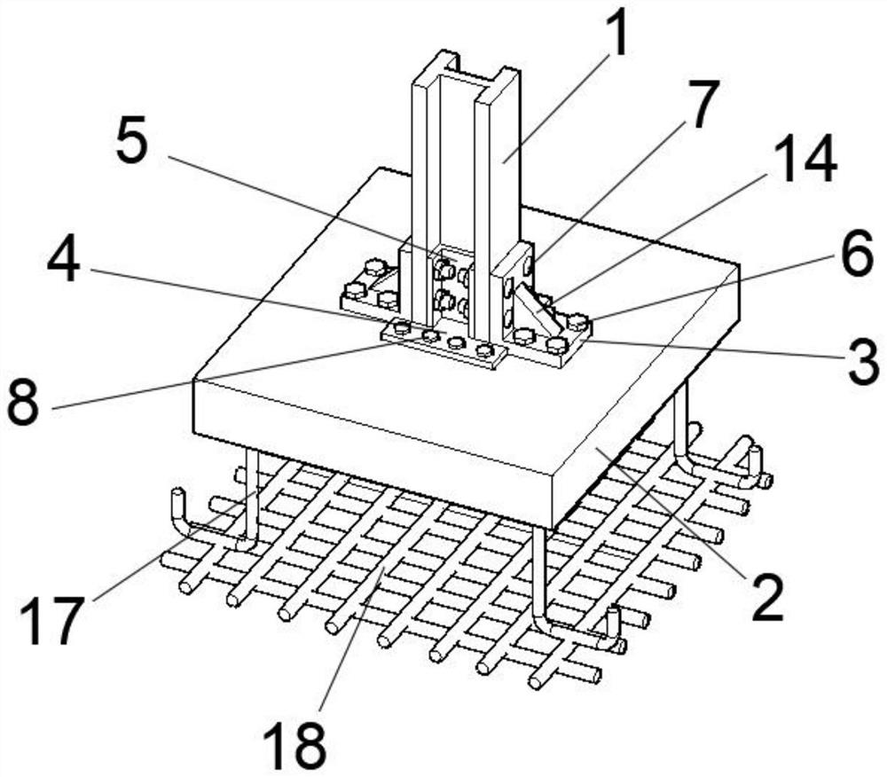
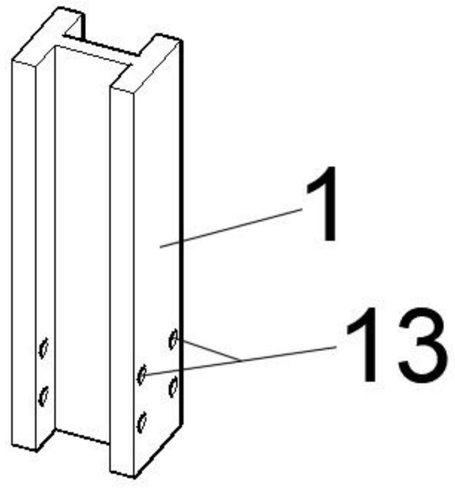
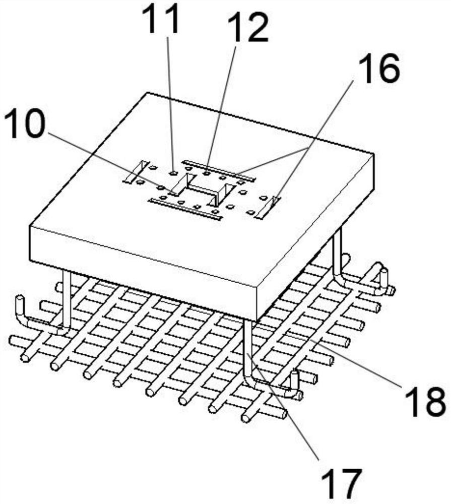
[0026] Such as Figure 1-7 As shown, the assembled joint between H-shaped steel column and base includes H-shaped steel column 1 and embedded base 2. The node also includes L-shaped connector 3 and combined connector. The flange plate side of H-shaped steel column 1 passes through The L-shaped connector 3 is connected to the embedded base 2, and the web side of the H-shaped steel column 1 is connected to the embedded base 2 through a combined connector, which includes an E-shaped connector 4 and a C-shaped connector. Part 5, one end of the C-shaped connector 5 is welded to the E-shaped connector 4, one side of the L-shaped connector 3 is connected to the embedded base 2 through a bolt 6, and the L-shaped connector 3 The other side is connected to...


PUM


Abstract

The invention discloses an H-shaped steel column and base assembled joint. The H-shaped steel column and base assembled joint comprises an H-shaped steel column and an embedded base; the joint furthercomprises an L-shaped connecting part and a combined connecting part; a flange plate side of the H-shaped steel column is connected with the embedded base through the L-shaped connecting part; a webside of the H-shaped steel co9lumn is connected with the embedded base through the combined connecting part; the combined connecting part comprises an E-shaped connecting part and a C-shaped connecting part; the end part of one end of the C-shaped connecting part is connected with the E-shaped connecting part in a welding way; one side of the L-shaped connecting part is connected with the embeddedbase through a bolt I; the other side of the L-shaped connecting part is connected with the C-shaped connecting part through a bolt II that penetrates through the flange plate of the H-shaped steel column; and the E-shaped connecting part is connected with the embedded base through a bolt III. According to the H-shaped steel column and base assembled joint disclosed by the invention, the H-shapedsteel column is installed by adopting an assembly type installation way; the H-shaped steel column is convenient to position and install; high accuracy and simple construction are achieved; the construction efficiency is improved; and the joint adopts assembly type installation, resists shearing and bending, is high in bearing strength and can meet the requirements of assembly type construction of steel structures.

Description

technical field [0001] The invention relates to the technical field of steel structure construction, in particular to an assembled node of an H-shaped steel column and a base and a construction method. Background technique [0002] In multi-story and high-rise steel structures, H-shaped steel beams and H-shaped steel columns are used as the main load-bearing components, especially the connection stability of H-shaped steel columns determines the overall strength of the steel structure. Most of the existing steel structure columns and bases are Through welding connection, the welding contact surface is small, the bearing strength is low, and the process requirements are high, and the construction is more complicated. In addition, the connection between the H-shaped steel column and the base requires precise positioning of the H-shaped steel column, and the H-shaped steel column is long and difficult to move. , The positioning is cumbersome and the construction efficiency is l...

Claims


Application Information

Patent Timeline
Patent Type & Authority Applications(China)
IPC IPC(8): E04B1/38E04B1/24
CPCE04B1/2403E04B1/38E04B2001/2406
Inventor 沈虎沈龙沈建东
Owner 安徽跨宇钢结构网架工程有限公司
Learn More