
Shallow draught floating type wind generating set foundation platform

A technology for wind turbines and basic platforms, which is used in wind power generation, floating buildings, ship parts, etc., can solve the problem of inability to meet the needs of offshore marine resource development, aggravate the difficulty of developing shallow water mooring systems, and arrange wind turbines, etc. problems, to achieve the effect of improving seafood quality and breeding efficiency, simple structure and safe use

Inactive Publication Date: 2020-09-18
山东中能华源海上风电集团有限公司
View PDF7 Cites 4 Cited by
  • Summary
  • Abstract
  • Description
  • Claims
  • Application Information

AI Technical Summary

Problems solved by technology

However, in the existing floating foundations, the column-stabilized semi-submersible foundation has limited buoyancy provided by the column, and the design draft is increased to form sufficient buoyancy to meet the needs of floating foundations and marine resource development equipment, so it is mostly used in deep waters in the offshore ;The damping pool foundation adopts a square hull type, and the square is not a stable shape, resulting in large main scale, large frontal area, and large environmental loads such as wind, wave and current, which exacerbates the difficulty of developing shallow water mooring systems; single column foundation and tension leg The foundations are typical deep-draft floating platforms used in deep water, which are not suitable for shallow waters along the coast of islands, and the structural form is not conducive to the simultaneous arrangement of wind turbines, wave energy generation devices and mariculture facilities on the foundation.
Therefore, the existing floating foundation cannot meet the needs of the development of my country's coastal marine resources.

Method used


Image

  • Shallow draught floating type wind generating set foundation platform
  • Shallow draught floating type wind generating set foundation platform
  • Shallow draught floating type wind generating set foundation platform

Examples


Embodiment Construction

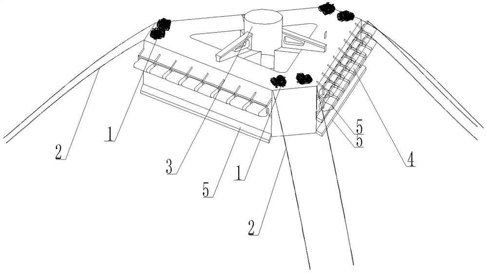
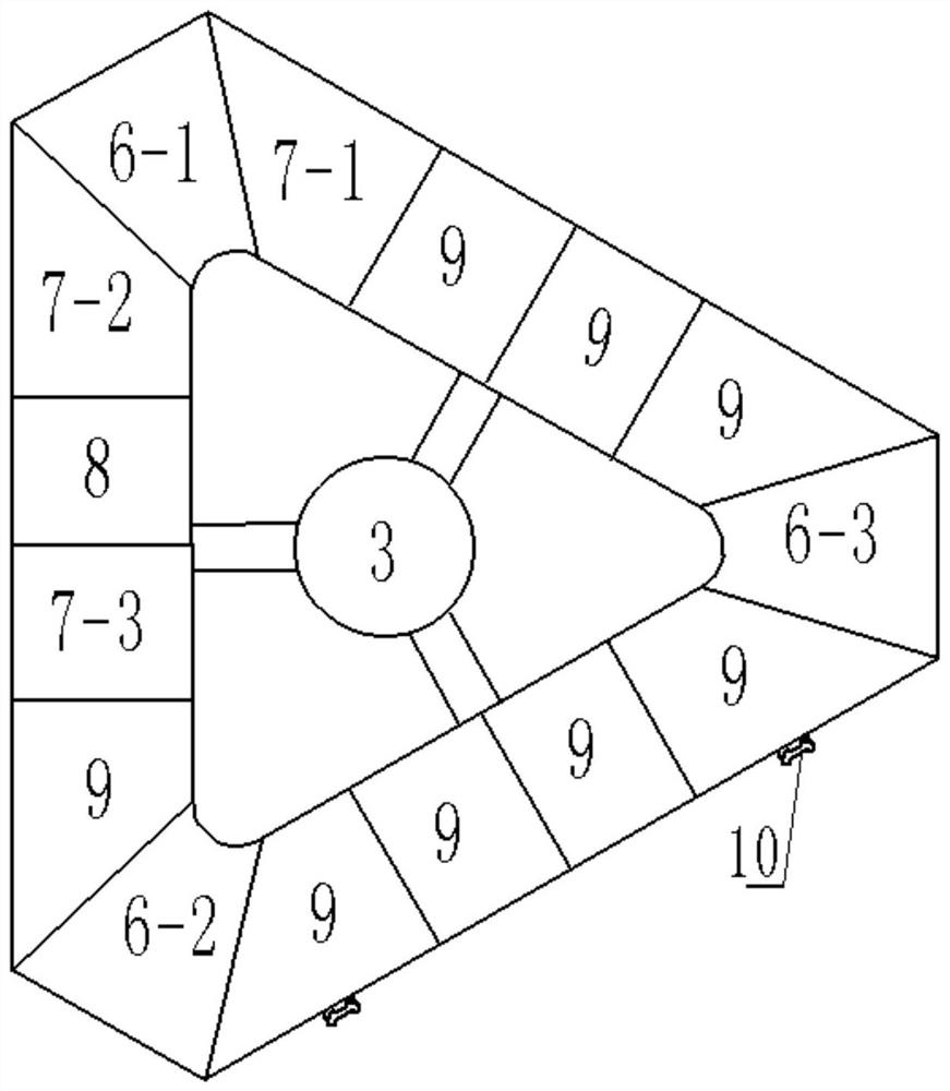
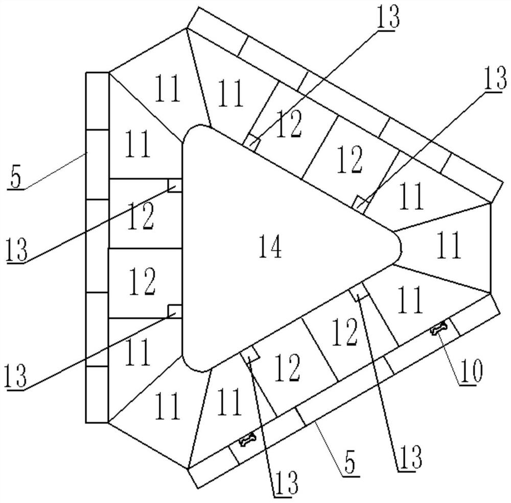
[0019] figure 1 , figure 2 with image 3 As shown, the foundation platform of the shallow-draft floating wind turbine is a triangular barge type, including a hull and a mechanical cabin. The hull is a triangular ring with a triangular outside and a triangular hollow area in the middle; the hull has a two-layer structure, namely the upper part of the hull and the lower part of the hull; the mechanical cabins are distributed inside the upper part of the hull and the lower part of the hull. The mechanical compartments include anchor chain compartments 6-1, 6-2, 6-3, electromechanical equipment compartments 77-1, 7-2, 7-3, electrical equipment compartments 8, empty compartments 9, solid ballast compartments 11 and Ballast water tank 12. The anchor chain cabins 6-1, 6-2, 6-3, electromechanical equipment cabins 77-1, 7-2, 7-3, electrical equipment cabins 8 and empty cabins 9 are located on the upper part of the hull; the solid ballast tanks 11 and the ballast water tank 12 are ...


PUM


Abstract

The invention discloses a shallow draught floating type wind generating set foundation platform which is of a triangular barge type and comprises a hull and a mechanical cabin arranged in the hull. The hull is divided into a hull upper part and a hull lower part; the mechanical cabin at the upper part of the hull comprises chain lockers, an electromechanical equipment cabin, an electrical equipment cabin and an empty cabin; the three chain locker bodies are arranged at the three vertex angles of the hull respectively. The mechanical cabin on one side of one chain locker is sequentially provided with an electromechanical equipment cabin, an electrical equipment cabin and an electromechanical equipment cabin; a mechanical cabin on the other side of the chain locker is an electromechanical equipment cabin; the rest cabins are empty cabins; a mechanical cabin in the middle of the upper portion of the hull is a wind power control equipment cabin, and a wind turbine generator installation base is fixed to the upper portion of the wind power control equipment cabin. The foundation platform adopts a triangular barge type as the foundation platform, has the characteristics of simple structure, shallow draft, stable floating, safety in use and the like, and is particularly suitable for being used in an offshore shallow water environment.

Description

technical field [0001] The invention relates to a base platform of a generator set, in particular to a base platform of a shallow-draft floating wind power generator set. Background technique [0002] The existing floating foundations used for marine resources development mainly include four types: column-stabilized semi-submersible foundations, damping pool foundations, single-column foundations, and tension leg foundations. The column-stabilized semi-submersible foundation is composed of multiple stabilizing columns providing buoyancy and diagonal braces between the stabilizing columns. The interior of the stabilizing columns is provided with a ballast tank, and the bottom of the stabilizing columns is provided with a heave structure; Mooring positioning equipment and other equipment. The foundation of the damping pool is a square barge-shaped platform, with a square moon pool in the center, and wind power generators, mooring and positioning equipment and other equipment ...

Claims


Application Information

Patent Timeline
IPC IPC(8): B63B35/44B63B3/14B63B21/50
CPCB63B3/14B63B21/50B63B35/44B63B2003/147B63B2035/446B63B2035/4466Y02E10/727
Inventor 刘宁川
Owner 山东中能华源海上风电集团有限公司
Learn More