Subsurface gate processing technology

A latent gate and processing technology, applied in electric processing equipment, metal processing equipment, manufacturing tools, etc., can solve the problems of difficult placement, difficult to archive, large pressure loss, etc., to avoid manual clamping and The effect of disassembly and assembly, improving the degree of automatic production and reducing the difficulty of clamping

Inactive Publication Date: 2020-09-18
NINGBO JOYSONQUIN AUTOMOTIVE SYST HLDG CO LTD
View PDF5 Cites 1 Cited by
  • Summary
  • Abstract
  • Description
  • Claims
  • Application Information

AI Technical Summary

Problems solved by technology

(2) After the product is formed, it will be automatically broken with the plastic part when it is ejected
Its disadvantages are as follows: (1) Since the latent gate sneaks under the parting surface and enters the cavity along an oblique direction, it is difficult to process
(2) Since the shape of the gate is a cone, it is easy to cut off when ejecting, so the diameter should be relatively small, but when dealing with thin-walled products, it is not suitable because the pressure loss is too large and it is easy to condense.
[0004] At present, the processing of the latent glue inlet is processed by the swing angle of the workpiece or the swing angle of the electrode; in the process, it is necessary to manually adjust the gauge of the part or the electrode, and trim the edge of the workpiece, and then process it on the machine. The main defect is that the process is cumbersome. , there are many human interventions and manual operations are more troublesome, and it is not easy to archive
[0005] A Chinese patent (publication number: CN102151919B) discloses a method of electric discharge machining latent gate, which can process latent gate by electric discharge, but in this method, it is necessary to match the pouring direction of the insert with the spark machine The workbenches are perpendicular to each other. Due to the high requirements on the placement position of the inserts, the placement method is difficult, and the final gate accuracy is difficult to be guaranteed.

Method used


Image

  • Subsurface gate processing technology
  • Subsurface gate processing technology
  • Subsurface gate processing technology

Examples


Embodiment Construction

[0032] The present invention is further explained in conjunction with the accompanying drawings.

[0033] see figure 1 A kind of latent gate processing technology shown, comprises the following steps:

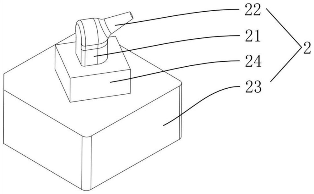
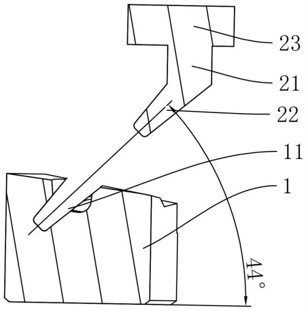
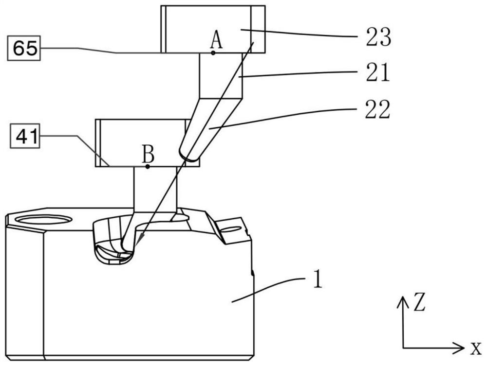
[0034] a. Manufacture an integrated electrode according to the shape of the gate, wherein the integrated electrode includes a reference platform, a connecting part formed on the reference platform, and an electrode head formed by extending the end of the connecting part obliquely outwards, the integrated electrode It also includes a reinforcement seat formed between the reference platform and the connection part to strengthen the strength of the connection part. Since the electrode tip and the workpiece will be subjected to contact discharge machining during processing, the connection part and the connection part will be strengthened by setting the reinforcement part. The strength of the electrode tip is to avoid damage during processing. The bottom surface of the reference pl...


PUM


Abstract

The invention discloses a subsurface gate processing technology. The subsurface gate processing technology comprises the following steps that a, an integrated electrode is manufactured according to the gate shape, wherein an electrode head matched with the gate shape is arranged on the integrated electrode; b, the integrated electrode is installed on a machine head of an electric discharge machine, and a gate axis line of a to-be-processed workpiece coincides with an axis line of the electrode head of the integrated electrode; c, according to the initial installation position of the electrodehead of the integrated electrode, processing starting coordinates are determined by the position of a point on the integrated electrode, when processing of the electrode head of the integrated electrode is finished, the electrode head of the integrated electrode is located in a gate, and processing ending coordinates are determined by the position of the point on the integrated electrode; and d, the starting processing coordinates and the ending processing coordinates are input on the electric discharge machine. According to the subsurface gate processing technology, the electrode precision ishigh, the discharge quality is good, processing is convenient, manual clamping and disassembly are omitted, and the degree of automatic production is improved.

Description

technical field [0001] The invention relates to the technical field of processing technology, in particular to a latent gate processing technology. Background technique [0002] Latent gate, also known as tunnel gate, is evolved from point gate. It not only overcomes the shortcomings of point gate mold complexity, but also maintains the advantages of point gate. The latent gate can be set on the side of the movable mold or on the side of the fixed mold. It can be placed on the inner surface or hidden side of the plastic part, it can also be placed on the ribs and columns of the plastic part, and it can also be placed on the parting surface. It is also a simple and easy way to use the ejector rod of the mold to set the gate. The latent gate is generally in the shape of a cone, and forms a certain angle with the cavity, usually 20°-45°, and the gate size can be selected according to the size of the point gate. [0003] The advantages of latent gates are as follows: (1) The ...

Claims


Application Information

Patent Timeline
Patent Type & Authority Applications(China)
IPC IPC(8): B23H1/00B23H11/00
CPCB23H1/00B23H11/00
Inventor 徐道平段海军
Owner NINGBO JOYSONQUIN AUTOMOTIVE SYST HLDG CO LTD
Why Eureka
Try Eureka