Mechanical part drilling device

A technology for drilling equipment and mechanical accessories, which is applied in the direction of drilling/drilling equipment, boring/drilling, metal processing equipment, etc., and can solve the problems of no drill locking mechanism and no tool change mechanism, etc., to achieve improved Drilling efficiency and the effect of reducing labor costs

Active Publication Date: 2020-09-18
鲁仲斐
View PDF19 Cites 4 Cited by
  • Summary
  • Abstract
  • Description
  • Claims
  • Application Information

AI Technical Summary

Problems solved by technology

[0003] In the Chinese invention patent document whose publication number is CN108526526B, a kind of drilling equipment for mechanical accessories is disclosed. The equipment performs multi-station drilling by setting a flywheel. During the specific drilling operation, a drilling machine is used for drilling, but the The equipment is not equipped with a convenient tool change mechanism, that is, it can be convenient and fast to change the tool if the drill needs to be different, and use different sizes of drill bits for drilling. In addition, there is no detailed description of the locking mechanism of the drill bit, that is, the drill bit is in the process of drilling. During the hole process, the drill bit can be locked tightly and will not slip

Method used


Image

  • Mechanical part drilling device
  • Mechanical part drilling device
  • Mechanical part drilling device

Examples


Embodiment 1

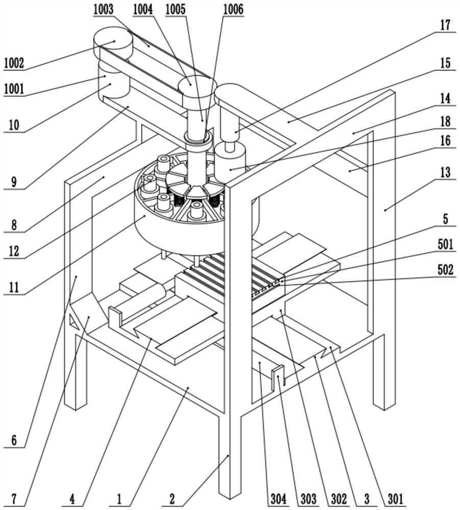
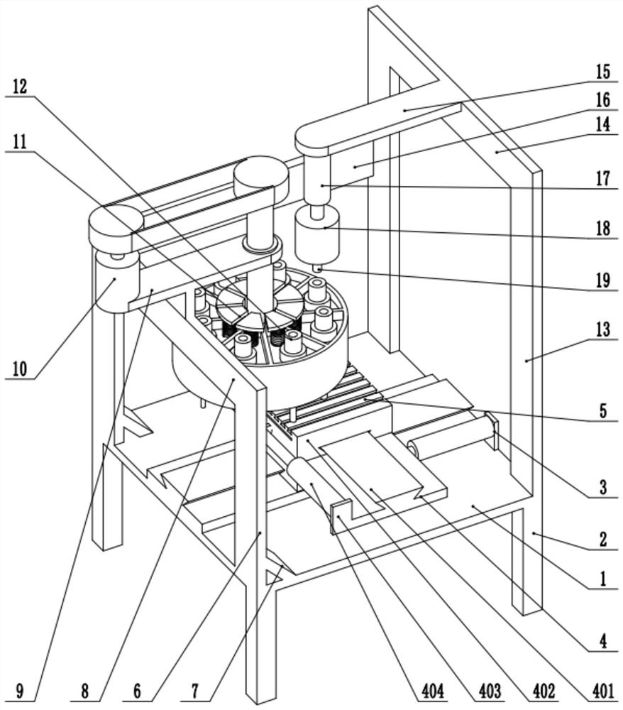
[0026] see Figure 1-6 , drilling equipment for mechanical accessories, including a base 1, the lower surface of the base 1 is fixedly connected to four support legs 2, the upper surface of the base 1 is fixedly connected to a transverse feed mechanism 3, and the upper surface of the transverse feed mechanism 3 is fixedly connected to a longitudinal feed mechanism 4. The upper surface of the longitudinal feed mechanism 4 is fixedly connected to the clamping seat 5, the upper surface of the base 1 is fixedly connected to two left vertical plates 6, the upper part of the left vertical plate 6 is fixedly connected to the left horizontal plate 8, and the left horizontal plate 8 is fixedly connected to the left vertical plate 8. Mounting seat 9, the upper surface of the left mounting seat 9 is fixedly connected to the tool changing mechanism 10, the lower part of the tool changing mechanism 10 is fixedly connected to the cutterhead 11, the upper part of the cutterhead 11 is fixedly ...

Embodiment 2

[0035] see Figure 1-6 , the other content of this embodiment is the same as that of Embodiment 1, except that: the right side of the left vertical bar 6 is fixedly connected to the support plate 7, the support plate 7 is fixedly connected to the base 1, and the left vertical plate 6 and the right vertical plate 13 The connection plate 16 is fixedly connected between them.

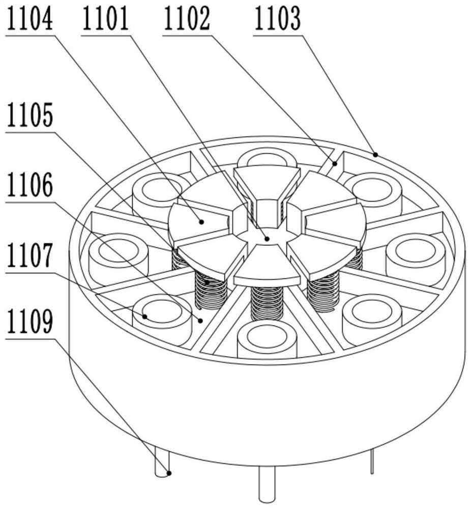
[0036] In the implementation process of the present invention, firstly, the mechanical parts are fixed on the clamping and fixing base 5. At this time, the horizontal feed mechanism 3 and the longitudinal feed mechanism 4 are adjusted to move the position where the mechanical parts need to be drilled to directly below the drill bit 1109. At this time, select a suitable drill bit according to the size of the hole to be drilled, that is, turn on the servo motor 1001 to drive the tool change shaft 1005 to rotate, and at this time drive the cutter head 11 to rotate. Right below, at this time, the first electr...


PUM


Abstract

The invention discloses a mechanical part drilling device and relates to the technical field of machining. The mechanical part drilling device comprises a base. The lower surface of the base is fixedly connected with supporting legs. The upper surface of the base is fixedly connected with a transverse feeding mechanism. The upper surface of the transverse feeding mechanism is fixedly connected with a longitudinal feeding mechanism. The upper surface of the longitudinal feeding mechanism is fixedly connected with a clamping and fixing seat. The upper surface of the base is fixedly connected with left vertical plates. The upper portions of the left vertical plates are fixedly connected with a left transverse plate. The upper portion of the left transverse plate is fixedly connected with a left mounting base. The upper surface of the left mounting base is fixedly connected with a tool changing mechanism. The tool changing mechanism is fixedly connected with a cutter head. The upper portion of the cutter head is fixedly connected with a locking mechanism. The upper surface of the base is fixedly connected with right vertical plates. The upper portions of the right vertical plates are fixedly connected with a right transverse plate. The right transverse plate is fixedly connected with a right mounting bas. The lower portion of the right mounting base is fixedly connected with a first electric push rod. The first electric push rod is fixedly connected with a motor. According to the mechanical part drilling device, a drill bit can be replaced conveniently through the tool changingmechanism, cutting tools can be used rapidly through the cutter head, the drilling efficiency is improved, and the labor cost is lowered.

Description

technical field [0001] The invention relates to the technical field of mechanical processing, in particular to drilling equipment for mechanical accessories. Background technique [0002] Drilling refers to the operation of machining a hole in a solid material with a drill. When drilling mechanical parts, a drilling machine is mainly used for drilling operations. A drilling machine refers to a machine tool that mainly uses a drill bit to process holes on a workpiece. Generally, the rotation of the drill bit is the main movement, and the axial movement of the drill bit is the feed movement. The drilling machine has a simple structure and relatively low machining accuracy. It can drill through holes and blind holes, replace special tools, expand, countersink, ream or tap. During the machining process, the workpiece does not move, let the tool move, align the center of the tool with the center of the hole, and make the tool rotate (main movement). The characteristic of the d...

Claims


Application Information

Patent Timeline
IPC IPC(8): B23B39/14B23B47/00
CPCB23B39/14B23B47/00
Inventor 鲁仲斐胡嘉侃
Owner 鲁仲斐
Why Eureka
Try Eureka