Bending part dual-face punching mold

A bending and punching technology, which is applied in the field of double-sided punching molds for bending parts, can solve problems such as inability to punch holes, achieve the effect of ensuring punching quality and improving punching efficiency

Inactive Publication Date: 2020-09-18
黄伟岳
View PDF9 Cites 0 Cited by
  • Summary
  • Abstract
  • Description
  • Claims
  • Application Information

AI Technical Summary

Problems solved by technology

However, the above-mentioned punching dies can only perform double-sided punching for axially arranged parts, and cannot be punched for those curved parts.

Method used


Image

  • Bending part dual-face punching mold
  • Bending part dual-face punching mold
  • Bending part dual-face punching mold

Examples


Embodiment 1

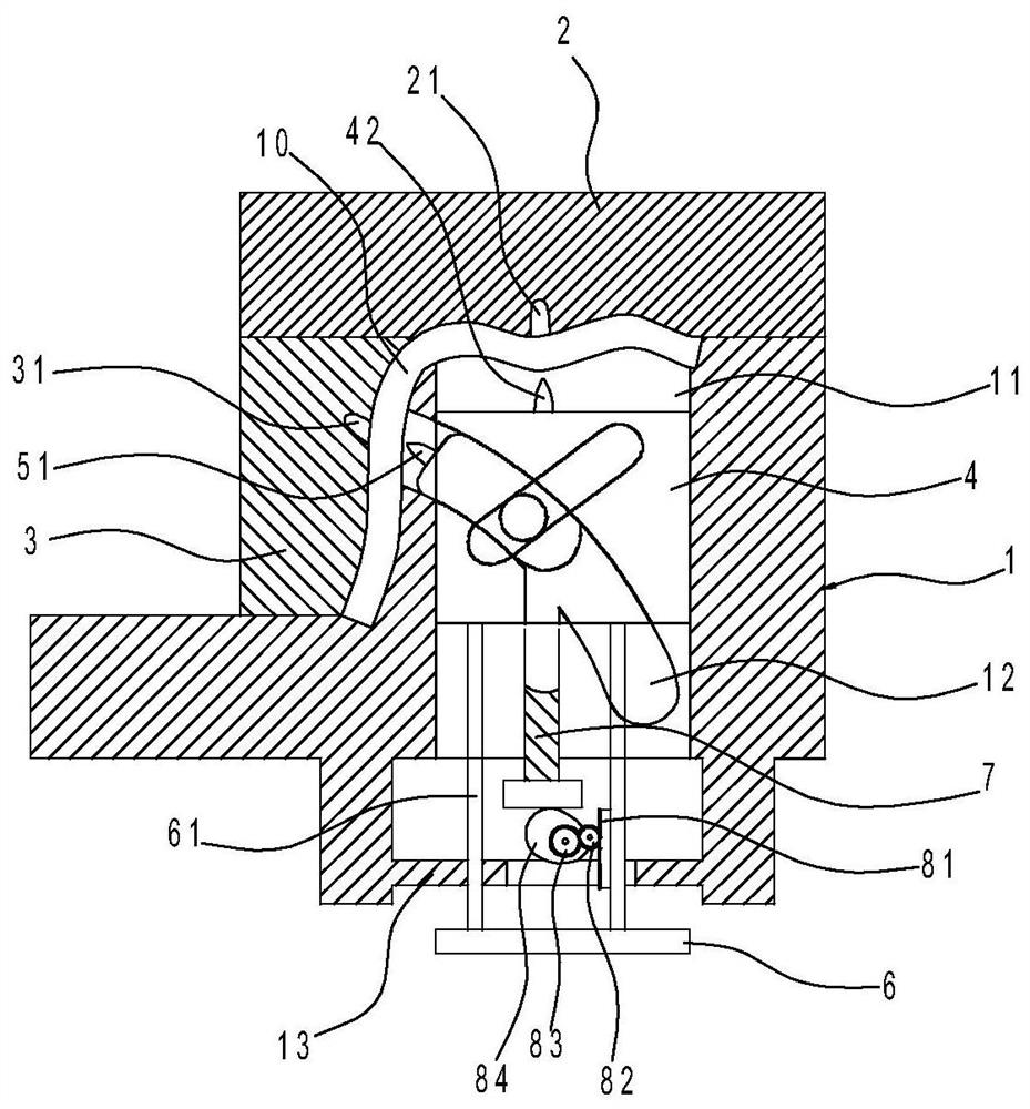
[0019] Such as Figures 1 to 5 As shown, the double-sided punching die for curved parts in this implementation includes a bottom mold 1, a top mold 2, a side mold 3, a vertical slider 4, a curved slider 5, a push plate 6 and a push rod 61.

[0020] Among them, when the bottom mold 1, the top mold 2 and the side mold 3 are closed, a cavity 10 matching the external shape of the curved part is formed inside, and an upper punching hole 21 is opened in the cavity of the top mold 2. A side punching hole 31 is provided in the cavity, a push plate 6 is arranged under the bottom mold 1, a push rod 61 is arranged on the push plate 6, a vertical slideway 11 arranged vertically is provided in the bottom mold 1, and the bottom mold 1 is provided with an arc-shaped slideway 12 opposite to the side punching hole 31, and a vertical slider 4 is slidably arranged in the vertical slideway 11, and an inclined slideway 41 is provided on the vertical slideway 4. On the arc-shaped slideway 12 The i...

Embodiment 2

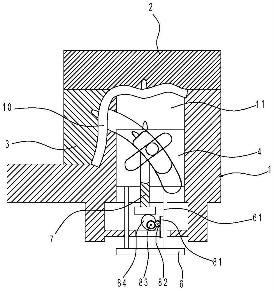
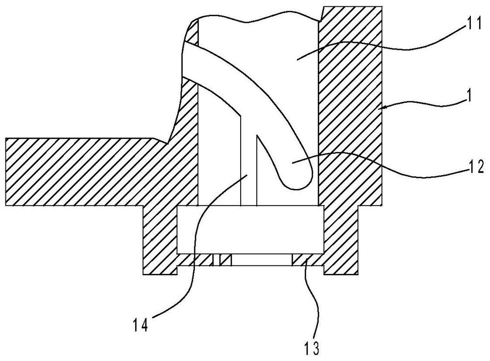
[0027] Such as Figure 6 and 7 As shown, the difference technical feature of embodiment 2 relative to embodiment 1 is that the ejector mechanism is different. The ejector mechanism in embodiment 2 is that a spacer 91 is arranged on the push plate 6, and a spacer 91 is set in the vertical slider 4. There is a sliding hole 14 communicating with the curved slider 5, and a push rod 7 is slidably arranged in the sliding hole 14, and the top of the push rod 7 is formed with a shape that is adapted to the bottom of the curved slider 5, and the bottom of the push rod 7 is provided with a The base plate 93 is provided with a bent rod 92 above the push plate 6 , one end of the bent rod 92 is hinged on the bottom mold 1 , and the other end of the bent rod 92 is located below the base plate 93 .

[0028] When the push plate 6 pushes the vertical slider 4 upward, the other end of the curved rod 92 pushes the base plate 93 to move upward. When the vertical slider 4 and the curved slider 5 ...


PUM


Abstract

The invention discloses a bending part dual-face punching mold. The mold comprises a bottom mold, a top mold and a side mold, when the bottom mold, the top mold and the side mold are assembled, a moldcavity matched with the shape of the outside of a bending part is formed internally, a push plate is arranged below the bottom mold, a push rod is arranged on the push plate, the mold is characterized in that a vertical sliding way which is vertically mounted is formed in the bottom mold, an arc sliding way opposite to a side punch hole is formed in the bottom mold, a vertical sliding block is slidingly mounted in the vertical sliding way, an inclined sliding way is formed on the vertical sliding block, a bending sliding block is slidingly mounted in the arc sliding way, a transmission columnlimited in the inclined sliding way is mounted on the bending sliding block, an upper puncher pin is arranged on the top of the vertical sliding block, a side puncher pin is arranged on the side wall, opposite to the side punch hole, of the bending sliding block, the push rod is connected with the vertical sliding block, according to the bending part dual-face punching mold, two side faces on a bending part can be subjected to one-time synchronous punching machining, and the punching efficiency is improved while the punching quality is ensured.

Description

technical field [0001] The invention relates to the field of punching, in particular to a double-sided punching die for curved parts. Background technique [0002] Die punching is a common means of cold processing workpieces. Existing die punching is generally aimed at single-sided punching on flat parts. For example, the existing publication number is CN106925662B Chinese Invention Patent "A Punching Die", which includes a lower die base, a die, a guide plate, an impact block and a punch; the lower die base has holes; The die is installed and limited on the lower die base, the die is provided with a blank placement position for positioning the blank, and the die is provided with a guide edge channel; the guide plate is installed and limited on the lower die base and located on the upper side of the die, the guide plate is provided with a punch guiding channel; the punch is accommodated in the punch guiding channel, and the punch is placed on the impact block Under the st...

Claims


Application Information

Patent Timeline
IPC IPC(8): B21D28/34B21D28/32
CPCB21D28/32B21D28/34
Inventor 黄伟岳
Owner 黄伟岳
Why Eureka
Try Eureka