Electromagnetic relay

An electromagnetic relay and relay technology, which is applied to electromagnetic relays, electromagnetic relay details, relays, etc., can solve the problems such as time-consuming overhaul of dismantling the casing, inability to obtain timely maintenance and repair, and reduced sensitivity of the control system, and achieve good protection effects. The effect of reducing finishing workload and improving maintenance efficiency

Inactive Publication Date: 2020-09-15
朱永安
View PDF0 Cites 0 Cited by
  • Summary
  • Abstract
  • Description
  • Claims
  • Application Information

AI Technical Summary

Problems solved by technology

Therefore, it plays the role of automatic adjustment, safety protection, conversion circuit, etc. in the circuit; most of the electromagnetic relay protection devices use bolts to install the protective shell to fix the relay. The bolts are easy to rust, which makes disassembly more troublesome, and the relay is easy to be damaged during the opening process, and it takes a lot of maintenance time to disassemble the shell. In some maintenance periods, the circuit is paralyzed and the sensitivity of the control system is reduced due to the lack of timely maintenance and repair. and, because the maintenance of relays in the prior art is usually live maintenance, and in the process of circuit maintenance, line replacement or wiring of the wiring board in the relay, there is usually a risk of electric shock due to improper operation; therefore, in order To improve the convenience of relay maintenance, the invention proposes an electromagnetic relay

Method used


Image

  • Electromagnetic relay
  • Electromagnetic relay
  • Electromagnetic relay

Examples


Embodiment Construction

[0027] In order to make the technical means, creative features, goals and effects achieved by the present invention easy to understand, the present invention will be further described below in conjunction with specific embodiments.

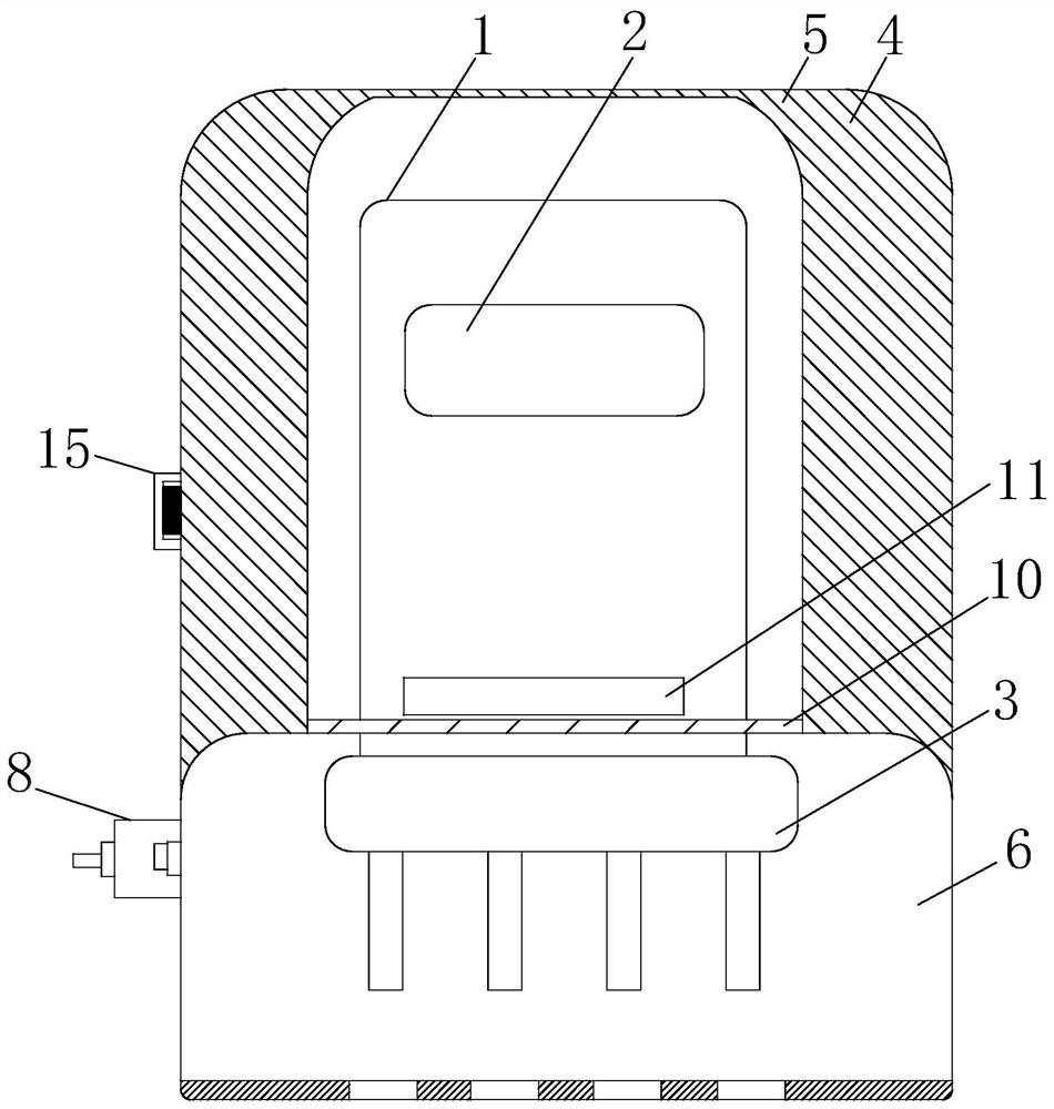
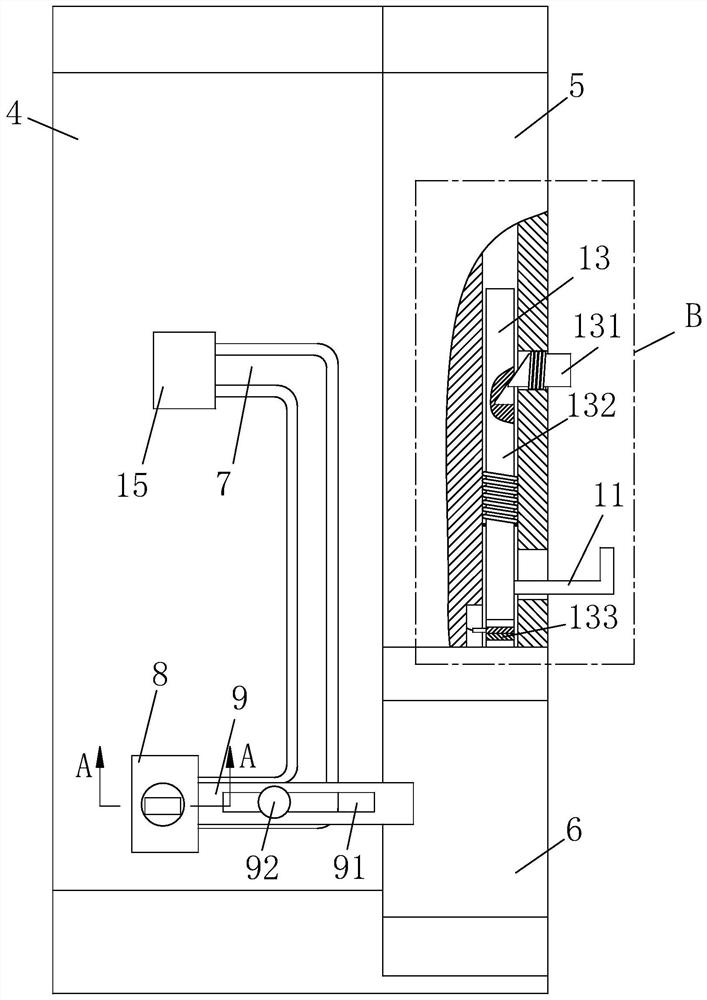
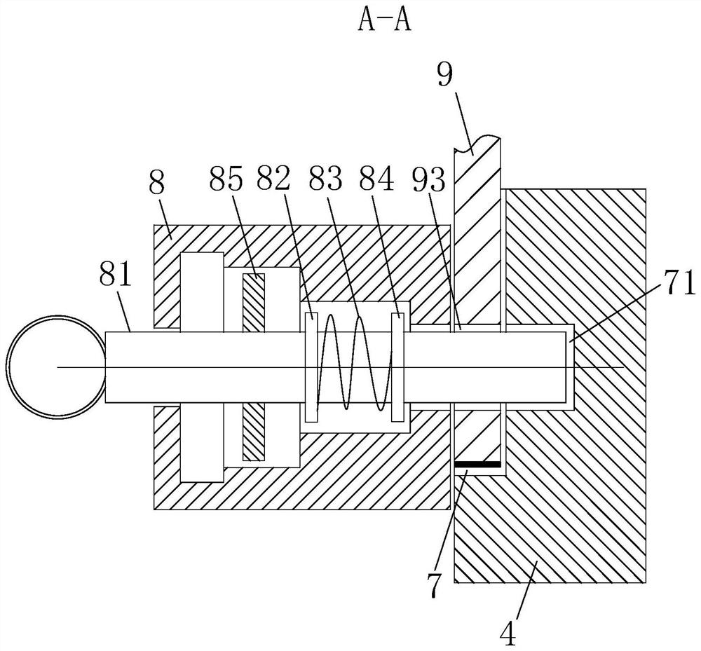
[0028] like Figure 1 to Figure 7 As shown, a kind of electromagnetic relay of the present invention comprises relay main body 1, display screen 2 and wiring board 3, and display screen 2 is installed on relay main body 1, and wiring board 3 is positioned at the below of relay main body 1; Said relay main body 1 and the outside of the wiring board 3 are equipped with a back cover 4, an upper cover 5, and a lower cover 6; the left and right ends of the back cover 4 are symmetrically provided with U-shaped chute 7; the lower end of the U-shaped chute 7 is provided with A fixed block 8 with a built-in chamber, and a plug-in module 8 provided in the chamber of the fixed block 8 is used to flexibly connect the lower cover 6;

[0029] The plug-in modul...


PUM


Abstract

The invention belongs to the technical field of relays, and particularly relates to an electromagnetic relay. The electromagnetic relay comprises a relay main body, a display screen and a wiring board, wherein the display screen is installed on the relay main body, and the wiring board is located below the relay main body; a rear cover, an upper cover and a lower cover are arranged outside the relay main body and the wiring board; U-shaped sliding grooves are symmetrically formed in the left and right ends of the rear cover; a fixing block with a built-in cavity is arranged at the end part ofthe lower end of the U-shaped sliding groove; and an inserting module arranged in the cavity of the fixing block is used for being movably connected with the lower cover. According to the invention, aprotection device of the relay can be disassembled or replaced more conveniently, the protection device is not prone to being damaged in the replacement process, and the safety of the maintenance process is improved.

Description

technical field [0001] The invention belongs to the technical field of relays, in particular to an electromagnetic relay. Background technique [0002] Electromagnetic relay is an electronic control device, which has a control system (also known as input circuit) and a controlled system (also known as output circuit), usually used in automatic control circuits, it actually uses low voltage and weak current circuits On and off, to control a kind of "automatic switch" of high voltage and strong current. Therefore, it plays the role of automatic adjustment, safety protection, conversion circuit, etc. in the circuit; most of the electromagnetic relay protection devices use bolts to install the protective shell to fix the relay. The bolts are easy to rust, which makes disassembly more troublesome, and the relay is easy to be damaged during the opening process, and it takes a lot of maintenance time to disassemble the shell. In some maintenance periods, the circuit is paralyzed a...

Claims


Application Information

Patent Timeline
Patent Type & Authority Applications(China)
IPC IPC(8): H01H50/02H01H50/04H01H50/12H01H50/14
CPCH01H50/023H01H50/041H01H50/047H01H50/12H01H50/14H01H2050/046
Inventor 朱永安沈金鹏陈刚
Owner 朱永安
Why Eureka
Try Eureka