Self-charging integrated rotating machinery rotating speed sensor and rotating speed calculation method thereof
A speed sensor and rotating machinery technology, applied in the sensor field, can solve the problems of inconvenient installation, the speed sensor cannot achieve self-power supply, and the cost is low, and achieves the effect of convenient installation, self-power supply, and remote signal transmission.
- Summary
- Abstract
- Description
- Claims
- Application Information
AI Technical Summary
Problems solved by technology
Method used
Image
Examples
Embodiment 1
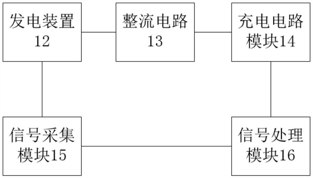
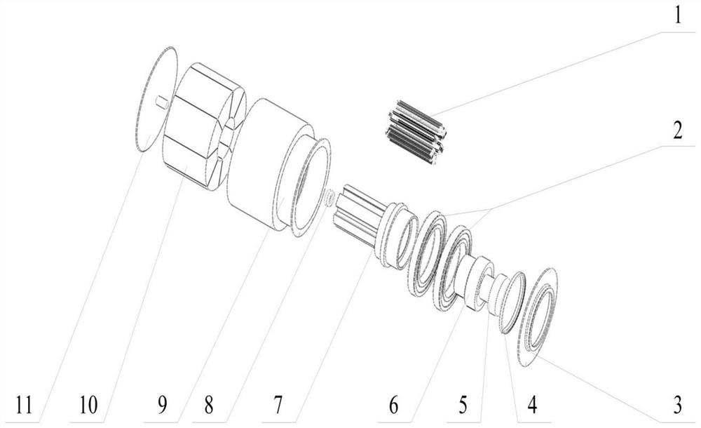
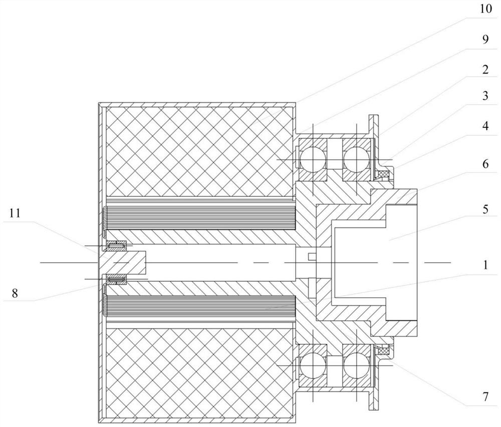
[0028] Embodiment 1: A self-charging integrated rotating machine speed sensor, such as figure 1 As shown, it includes the rotating main shaft of the gear box, the power generating device 12, the rectifier circuit 13, the charging circuit module 14, the signal acquisition module 15, the signal processing module 16 and the Bluetooth transmission module, and the power generating device 12 cooperates with the rotating main shaft of the gear box to generate an alternating current. The power generating device 12 is connected with the rectification circuit 13, the rectification circuit 13 is connected with the charging circuit module 14, and the charging circuit module 14 is connected with the signal processing module 16, such as Figure 5 As shown, the signal acquisition module 15 is connected with the power generation device 12, the signal acquisition module 15 collects the voltage signal of the power generation device, the signal acquisition device 15 is connected with the signal p...
Embodiment 2
[0034] Embodiment 2, a self-charging integrated rotating machine speed sensor. Compared with Embodiment 1, this embodiment adds fixed-value resistors R1, fixed-value resistors R2, fixed-value resistors R3, fixed-value resistors R4, and fixed-value resistors R5. , fixed-value resistor R6, triode K1, triode K2, triode K3, ohmmeter, first coil, second coil and third coil, the circumference of the permanent magnet ring 10 is divided into three equal-length circular arcs. The fixed value resistor R1, the fixed value resistor R2 and the fixed value resistor R3 are respectively installed at the intersection points of the fixed value resistor R1, the fixed value resistor R2 and the fixed value resistor R3 are connected in series with the ohmmeter, and the collector of the triode K1 is connected to the fixed value resistor R1 The emitter of the triode K1 is connected to the other end of the fixed value resistor R1 through the fixed value resistor R4, the base of the triode K1 is connect...
Embodiment 3
[0035] Embodiment 3, a self-charging integrated rotating machine speed sensor. Compared with Embodiment 1, this embodiment adds fixed-value resistors R1, fixed-value resistors R2, fixed-value resistors R3, fixed-value resistors R4, and fixed-value resistors R5. , fixed-value resistor R6, transistor K1, transistor K2, transistor K3, ohmmeter, first coil, second coil and third coil, divide the circumference of the rotating spindle of the gearbox into three arcs of equal length, and The fixed value resistor R1, the fixed value resistor R2 and the fixed value resistor R3 are respectively installed at the intersection points of the fixed value resistor R1, the fixed value resistor R2 and the fixed value resistor R3 are connected in series with the ohmmeter, and the collector of the triode K1 is connected to the fixed value resistor R1 The emitter of the triode K1 is connected to the other end of the fixed value resistor R1 through the fixed value resistor R4, the base of the triode ...
PUM
 Abstract
Description
Claims
Application Information
 - R&D
- Intellectual Property
- Life Sciences
- Materials
- Tech Scout
- Unparalleled Data Quality
- Higher Quality Content
- 60% Fewer Hallucinations
Browse by: Latest US Patents, China's latest patents, Technical Efficacy Thesaurus, Application Domain, Technology Topic, Popular Technical Reports.
© 2025 PatSnap. All rights reserved.Legal|Privacy policy|Modern Slavery Act Transparency Statement|Sitemap|About US| Contact US: help@patsnap.com


