
Loose joint device for screw-thread-free pipeline

A technology for pipes and unions, applied in the direction of pipes/pipe joints/fittings, flange connections, sleeve/socket connections, etc. It can solve problems such as unsealable, low pressure resistance, and difficulty in threading, and achieve enhanced sealing ability, the effect of enhancing the compressive strength

Pending Publication Date: 2020-09-15
HUNAN CHUANGHUA LOW CARBON ENVIRONMENTAL PROTECTION TECH
View PDF0 Cites 2 Cited by
  • Summary
  • Abstract
  • Description
  • Claims
  • Application Information

AI Technical Summary

Problems solved by technology

Small pipes are also connected with threaded buttons. If the pressure resistance is not high, socket-type connections can be used. For example, drain pipes and large-scale tap water pipes are inserted into the gaps with hemp rope, cement, or lead to seal. Grooved pipe button connections are common. Applied to the connection of medium-sized pipelines, such as the mutual connection of fire-fighting pipes. This connection requires the cooperation of pipe brackets to seal. Its connection form is difficult to bear the weight of the pipeline itself, and it is easy to cause the pipeline to sink and cannot be sealed. Use the pipe buckle that must be connected There is a load-bearing support nearby, and the larger the diameter of the pipe, the more difficult it is to thread
The current connection method is relatively simple in practicability, poor in sealing effect, poor in pressure resistance, and is not conducive to the maintenance of pipelines. Grooved pipe buckle connection requires groove pressing equipment, groove pressing equipment requires power supply, and hot melt connection also requires power supply, which will increase the work intensity of pipeline installation workers

Method used


Image

  • Loose joint device for screw-thread-free pipeline
  • Loose joint device for screw-thread-free pipeline
  • Loose joint device for screw-thread-free pipeline

Examples


Embodiment Construction

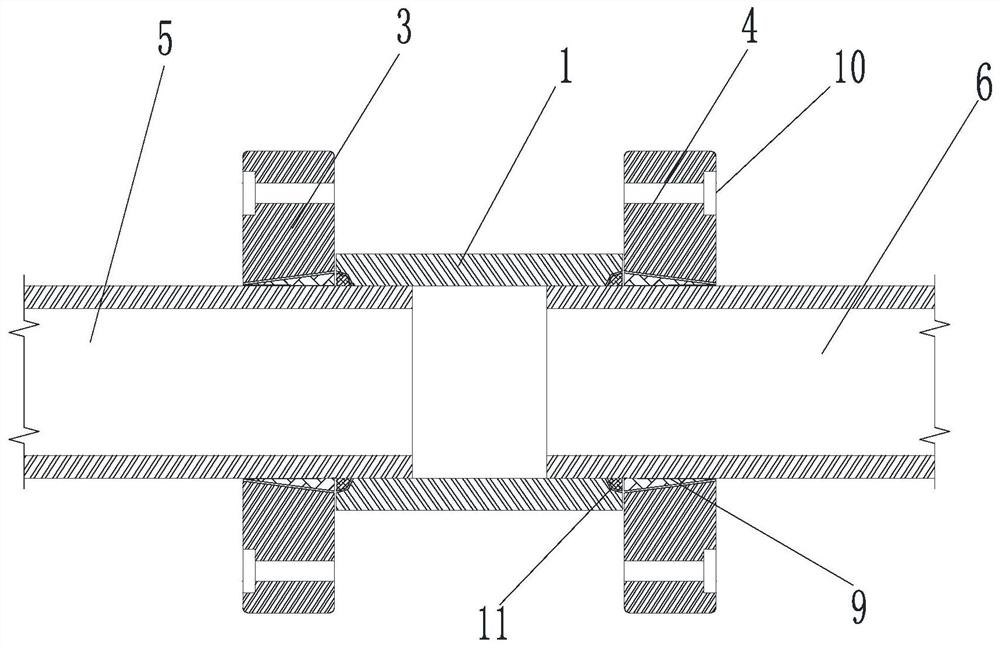
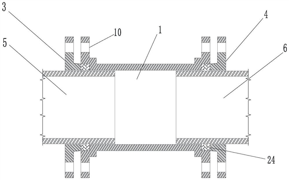
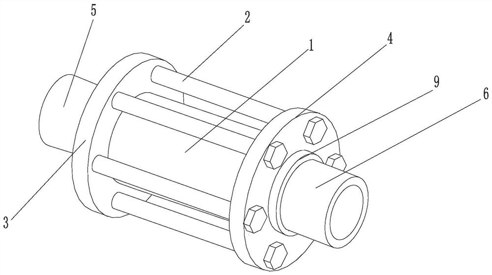
[0034] The following will combine Figure 1-14 The present invention is described in detail, and the exemplary embodiments and descriptions of the present invention are used to explain the present invention, but not to limit the present invention.

[0035] A threaded pipe joint device for connecting the first pipe 5 and the second pipe 6 is characterized in that it comprises a first locking flange 3, a second locking flange 4, a sealing pipe 1, a locking Screw 2 and tightening mechanism, a sealing tube 1 is sandwiched between the first locking flange 3 and the second locking flange 4, the tightening mechanism includes a tightening member and a sealing member, the first locking There are fasteners between the flange 3 and the first pipe 5, the second locking flange 4 and the second pipe 6, the sealing pipe 1 and the first locking flange 3, the second locking flange 4 There are seals at the compaction place, the locking screw 2 penetrates the first locking flange 3 and the seco...


PUM


Abstract

The invention relates to a screw thread-free pipeline loose joint device. The device is used for connecting a first pipeline and a second pipeline and is characterized by comprising a first locking flange, a second locking flange, a sealing pipe, a locking screw and a fastening mechanism, the sealing pipe is clamped between the first locking flange and the second locking flange, and the fasteningmechanism comprises a fastening piece and a sealing piece; fastening pieces are arranged between the first locking flange and the first pipeline and between the second locking flange and the second pipeline, sealing pieces are arranged at the compacted positions of the sealing pipe and the first locking flange and the compacted position of the sealing pipe and the second locking flange, and the locking screw sequentially penetrates through the first locking flange and the second locking flange and is close to the sealing pipe to be locked, and the sealing piece is pressed into gaps between thesealing pipe and the first pipeline and between the sealing pipe and the second pipeline. The device has the advantages of wide application field, labor hour saving, cost saving, pipe reutilization facilitation, convenient pipe network reconstruction and maintenance, sealing enhancement, and improvement of the pressure resistance level of the pipeline system.

Description

technical field [0001] The invention relates to the field of machinery, in particular to a threaded pipe joint device. Background technique [0002] In the construction of pipeline engineering, different connection methods should be selected according to the size and material of the pipes used. Ordinary steel pipes have threaded connections, welding and flange connections; seamless steel pipes, non-ferrous metal and stainless steel pipes are mostly welded and flanged; cast iron pipes are mostly socket connections, and a few use flange connections; plastic pipes are mostly threaded connections , bonding and hot melt connection, etc. Small pipes are also connected by threaded fasteners. If the pressure resistance is not high, socket-type connections can be used. For example, drainage pipes and large water pipes are inserted into the gaps and filled with hemp rope, cement, or lead sealing. Grooved pipe button connections are common. It is used in medium-sized pipeline connect...

Claims


Application Information

Patent Timeline
Patent Type & Authority Applications(China)
IPC IPC(8): F16L23/032F16L23/024F16L23/18F16L21/00
CPCF16L23/032F16L23/024F16L23/18F16L21/00
Inventor 刘小江刘赟
Owner HUNAN CHUANGHUA LOW CARBON ENVIRONMENTAL PROTECTION TECH
Learn More