
Novel motor train unit bogie replacing unit

A technology for EMUs and bogies, which is applied to lifts, lifting devices, roads, etc., can solve the problems of limited application scope, high construction cost, large engineering volume and cost, and achieve the effect of improving error tolerance.

Pending Publication Date: 2020-09-15
河北清铁机械设备制造有限公司
View PDF0 Cites 4 Cited by
  • Summary
  • Abstract
  • Description
  • Claims
  • Application Information

AI Technical Summary

Problems solved by technology

[0003] Since the entire train needs to be lifted to a certain height, the existing pit-type car crane has extremely high requirements on the synchronization of the bogie lifting device; at the same time, since the bogie lifting device and the car body lifting device are Fixedly installed on both sides of the carriage, the tolerance for train parking errors is extremely low (when the train stops, it is necessary to ensure that the bogie stops on the bogie lifting device, and also ensure that the position of the frame seat and the car body lifting device correspond Therefore, the requirements for the driver's parking operation are also extremely high; what's more, due to the certain distance between adjacent pits, in order to ensure the continuity of the lifting track and the fixed track, pit excavation and the entire truck The engineering quantity and cost of machine construction are relatively large; what's more, because the bogie lifting device and the car body lifting device are fixedly installed, the existing pit type car lifting machine is only suitable for trains with a specific car length. However, the types of trains produced in my country are not uniform. Therefore, the scope of application of the existing pit-type cranes is very limited and they all work on the ground, resulting in a large area for train maintenance bases and high construction costs.

Method used


Image

  • Novel motor train unit bogie replacing unit
  • Novel motor train unit bogie replacing unit
  • Novel motor train unit bogie replacing unit

Examples


Embodiment Construction

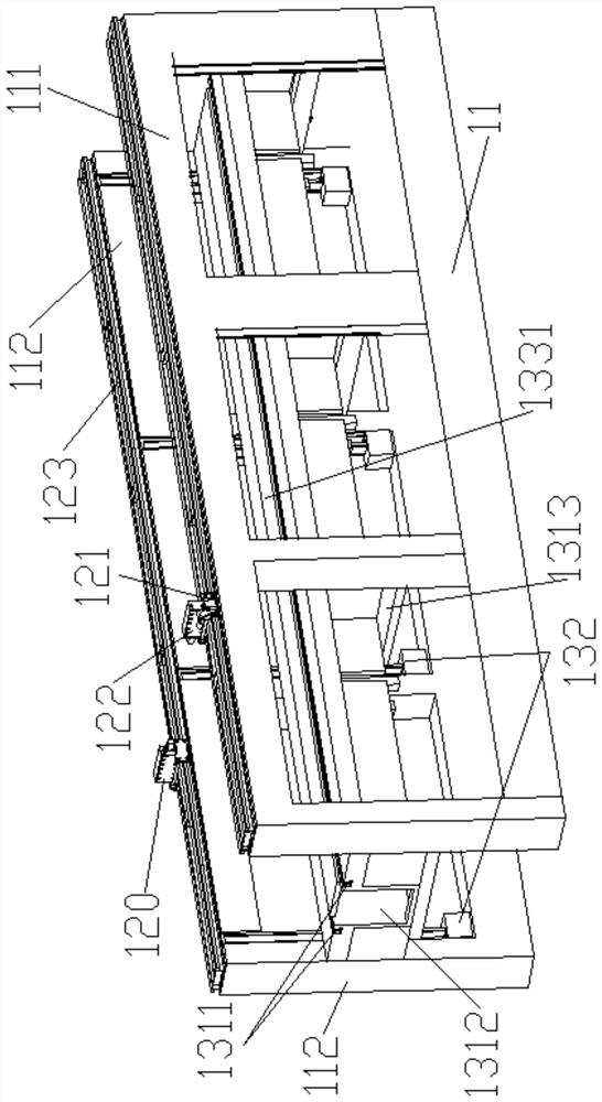
[0023] In order to make the object, technical solution and advantages of the present invention clearer, the present invention will be further described in detail below in conjunction with the accompanying drawings and embodiments. It should be understood that the specific embodiments described here are only used to explain the present invention, not to limit the present invention. In addition, the technical features involved in the various embodiments of the present invention described below can be combined with each other as long as they do not constitute a conflict with each other. In the present invention, for ease of description, up and down herein refer to up and down along the height direction of the compartment (i.e. the height direction), the track direction is the length direction of the compartment, and the width direction of the vehicle is the width direction of the compartment (i.e. the compartment left and right direction), which does not fully represent the actua...


PUM


Abstract

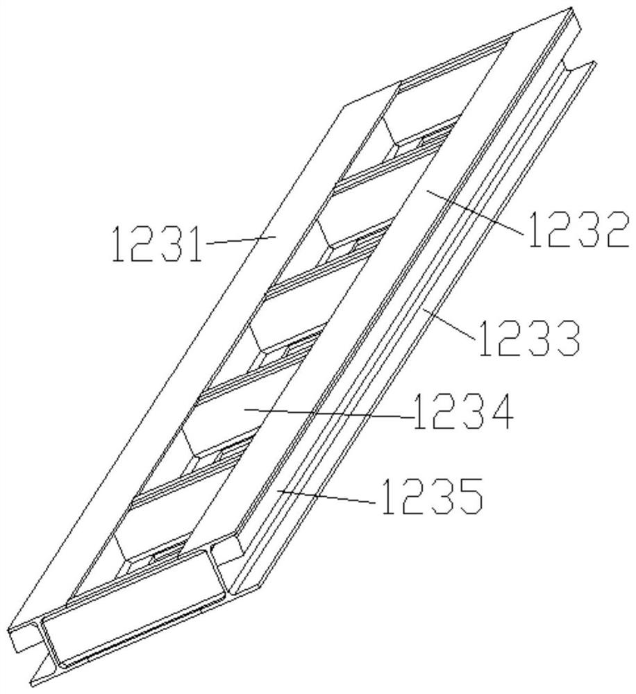
The invention discloses a novel motor train unit bogie replacing unit which comprises a main body framework, a supporting head mechanism and a ballast bed mechanism. A supporting head can be driven byitself along a supporting head walking rail so as to be aligned with a motor train unit lifting point. The ballast bed mechanism comprises a ballast bed and a lifting mechanism; the ballast bed is provided with a rail; and the lifting mechanism drives the ballast bed to reciprocate in a height direction so that the rail is selectively in butt joint with the fixed rail to form a continuous rail oris in butt joint with a negative working layer. When the lifting mechanism drives the ballast bed to be in a lifting state, the rail and the fixed rail are in butt joint to form the continuous rail.When the lifting mechanism drives the ballast bed to descend from the lifting state to a first descending state, the rail is in butt joint with the negative working layer, and the supporting head lifts a carriage. Synchronous lifting is easy to control, the unit is suitable for replacement operation of motor train unit bogies of all types, and an underground space can be effectively utilized for maintenance operation.

Description

technical field [0001] The invention belongs to the technical field of pit-type locomotives, and more specifically relates to a new bogie replacement unit for EMUs. Background technique [0002] Existing pit-type car cranes are equipped with bogie lifting devices with lifting rails and car body lifting devices arranged on both sides of the car body in several pits at a certain distance; There are fixed rails on the ground between the pits, and the adjacent lifting rails and fixed rails form a continuous rail, which is convenient for the carriage and the bogie to travel. Generally, two bogies are installed in one carriage, and one bogie needs to be equipped with two bogie lifting devices arranged on both sides of the car body. The train is lifted, the whole train leaves the ground and is raised to a certain height, and then raised to a certain height by the car body lifting device and stretched into the frame seats arranged on both sides of the train, and then the staff can ...

Claims


Application Information

Patent Timeline
IPC IPC(8): B61K13/00E01B1/00B66F7/10B66F7/28
CPCB61K13/00B66F7/10B66F7/28E01B1/00
Inventor 曹彬
Owner 河北清铁机械设备制造有限公司
Learn More