
Auxiliary gas path drying device and braking system

A drying device and brake system technology, which is applied in the direction of air handling devices, brakes, brake components, etc., can solve the problems of adverse effects of the main air circuit, rust of parts, insufficient pressure of the main air circuit, etc.

Active Publication Date: 2021-07-13
SANY AUTOMOBILE HOISTING MACHINERY
View PDF5 Cites 0 Cited by
  • Summary
  • Abstract
  • Description
  • Claims
  • Application Information

AI Technical Summary

Problems solved by technology

[0003] At present, the brake system only has a dryer on the main air path for air drying, but once the main air path drying device fails or the drying efficiency decreases, the air humidity of the brake system will increase, which will lead to rusting of parts in the air path Waiting for failure
Due to its own structural characteristics, if the dryer in the prior art is used in the auxiliary air path, it will easily lead to insufficient pressure in the main air path, thereby adversely affecting the main air path

Method used


Image

  • Auxiliary gas path drying device and braking system
  • Auxiliary gas path drying device and braking system
  • Auxiliary gas path drying device and braking system

Examples


no. 1 example

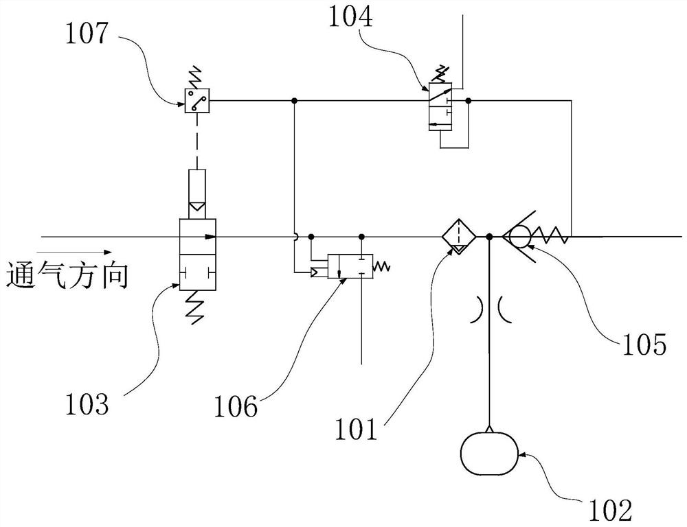
[0039] Please refer to figure 1 , this embodiment provides an auxiliary gas path drying device, which includes a first molecular sieve 101, a first regeneration cylinder 102, a first exhaust valve 106 and a control valve 103, and the first exhaust valve 106 and the first regeneration cylinder 102 are respectively Communicated with the first molecular sieve 101, the control valve 103 is arranged on the side of the air inlet of the first molecular sieve 101, and the control valve 103 is switched to a closed state when the pressure of the gas path exceeds the first threshold.

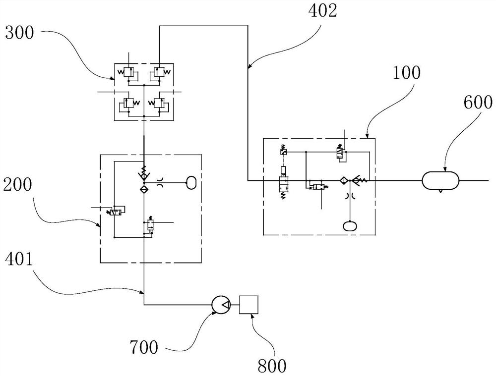
[0040] Such as figure 2 As shown, the auxiliary air path drying device 100 provided in this embodiment can be applied to the brake system, and can be applied to the auxiliary air path 402 of the brake system to dry the gas in the auxiliary air path 402, even in the manufacturing The main gas path 401 of the dynamic system has already been equipped with drying equipment, and the auxiliary gas path drying ...

no. 2 example

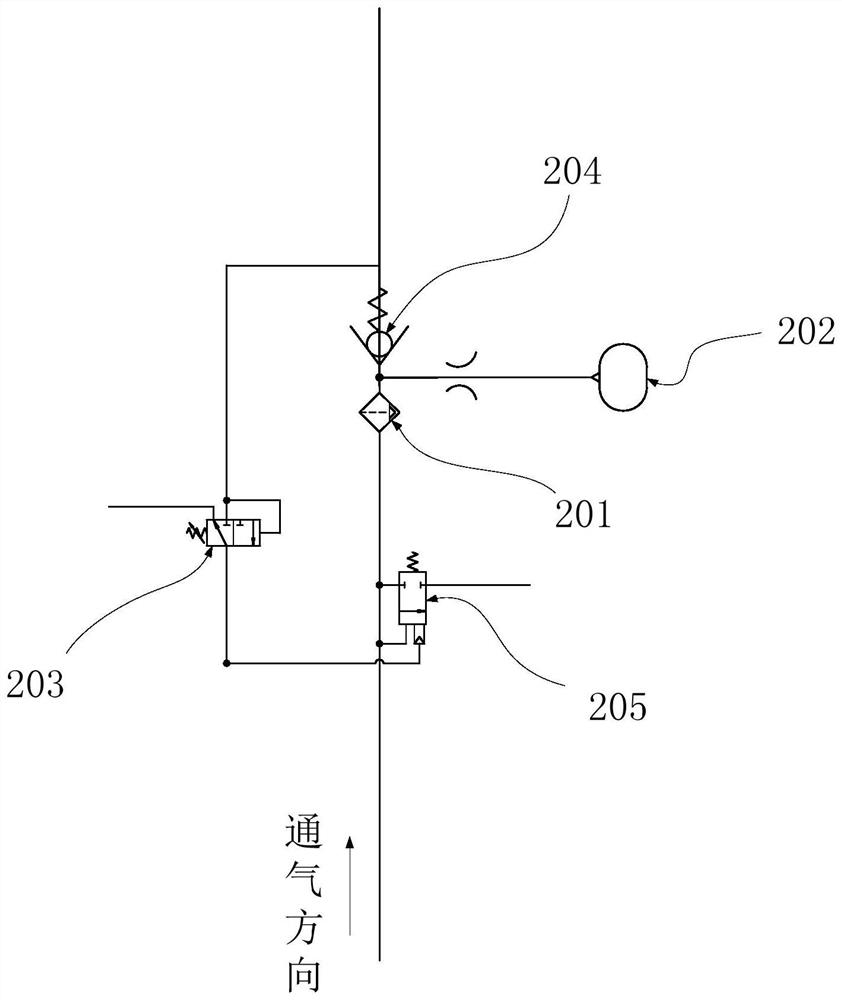
[0053] Such as figure 2 and image 3 As shown, this embodiment provides a brake system, which includes a main air circuit 401 and an auxiliary air circuit 402, and the auxiliary air circuit 402 is provided with the auxiliary air circuit drying device 100 provided in the first embodiment above.

[0054] Since the auxiliary air path 402 is provided with the auxiliary air path drying device 100, in the braking system provided by this embodiment, the gas in the auxiliary air path 402 can be dried without affecting the gas in the main air path 401. pressure.

[0055] Further, an air storage tank 600 may also be provided in the auxiliary air passage 402. The air storage tank 600 is arranged on the auxiliary air passage 402 at the side of the gas outlet of the auxiliary air passage drying device 100, and is dried by the auxiliary air passage drying device 100. The final gas enters the gas storage tank 600. The gas storage tank 600 can temporarily store gas, and the gas in the gas...


PUM


Abstract

An auxiliary gas path drying device and braking system, relating to the technical field of gas path drying devices, the auxiliary gas path drying device includes a first molecular sieve, a first regeneration cylinder, a first exhaust valve and a control valve, the first The regeneration cylinder and the first exhaust valve are respectively communicated with the first molecular sieve, the control valve and the first molecular sieve are both installed in the gas path, and the control valve is arranged on the air inlet side of the first molecular sieve , the control valve is switched to a closed state when the pressure of the air circuit exceeds a first threshold. The auxiliary air path drying device is applied to the auxiliary air path of the brake system, which can further dry the auxiliary air path without affecting the pressure of the main air path.

Description

technical field [0001] The invention relates to the field of gas path drying devices, in particular to an auxiliary gas path drying device and a braking system. Background technique [0002] According to the working medium, the brake system can be divided into three types: air brake, hydraulic brake and air top oil brake. Among them, the braking system of the air brake has the advantages of no pollution and convenient maintenance, and has relatively many applications. In the brake system of air brake, it is necessary to dry the gas in the air circuit. [0003] At present, the brake system only has a dryer on the main air path for air drying, but once the main air path drying device fails or the drying efficiency decreases, the air humidity of the brake system will increase, which will lead to rusting of parts in the air path Wait for failure. Due to its own structural characteristics, if the dryer in the prior art is used in the auxiliary gas path, it will easily lead to ...

Claims


Application Information

Patent Timeline
Patent Type & Authority Patents(China)
IPC IPC(8): B60T17/00
CPCB60T17/002
Inventor 卢环宇何全文吴彬
Owner SANY AUTOMOBILE HOISTING MACHINERY
Learn More