Potato shredding device
A potato and shredded technology, which is applied in metal processing and other fields, can solve the problems of easily damaged hands and achieve the effect of easy collection and improved efficiency
- Summary
- Abstract
- Description
- Claims
- Application Information
AI Technical Summary
Problems solved by technology
Method used
Image
Examples
Embodiment 1
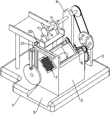
[0033] A potato shredding device, such as figure 1 As shown, it includes a base 1, a V-groove support 2, an inclined plane 5, a transmission mechanism 6 and a cutting mechanism 7, a V-groove support 2 is installed on the right side of the top of the base 1, an inclined plane 5 is provided on the right front side of the base 1, and the base 1. A transmission mechanism 6 is installed on the rear side of the right part, and a cutting mechanism 7 is arranged on the front part of the V-groove support 2 and the components of the transmission mechanism 6.
[0034] When it is necessary to cut potatoes into shreds, manually place the potatoes on the V-groove support 2, place the collection frame on the slope 5, and then start the parts of the transmission mechanism 6. The parts of the transmission mechanism 6 rotate counterclockwise first, and the cutting mechanism The parts of 7 move forward accordingly, and the parts of cutting mechanism 7 move forward to drive the potatoes forward, ...
Embodiment 2
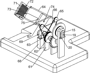
[0036] refer to Figure 1-3 As shown in the diagram, the transmission mechanism 6 includes a third bearing seat 61, a first transmission shaft 62, a main pulley 63, a screw mandrel 64, a secondary pulley 65, a flat belt 66, a triangular nut 67, a spacer 68 and a servo motor 69, The rear side of the right part of the base 1 is equipped with a third bearing seat 61, the upper part of the third bearing seat 61 is provided with a first transmission shaft 62, the middle part of the first transmission shaft 62 is equipped with a main pulley 63, and the left and right sides of the front wall of the V-groove support 2 Both sides are all provided with screw mandrel 64, and the rear end of screw mandrel 64 on both sides is all provided with secondary pulley 65, and is all wound with flat belt 66 between main pulley 63 and the secondary pulley 65 of both sides, and screw mandrel 64 on both sides There are triangular nuts 67 threaded between the rear parts, a spacer 68 is installed at the...
Embodiment 3
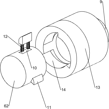
[0041] Specifically as Figure 1-4 As shown, it also includes a first bearing seat 3, a second bearing seat 4, a fourth bearing seat 8, a second transmission shaft 9, a wedge-shaped slider 11, an elastic member 12, a sleeve 13, a first rotating shaft 15, and a disc 16. Protruding column 17, driving lever 18, hexagonal block 19, spring clip 20, second rotating shaft 21, belt drive assembly 22, supporting column 23, feeding plate 24 and dial 25, base 1 right rear side is provided with There is a first bearing seat 3, a second bearing seat 4 is arranged on the rear right side of the base 1, the second bearing seat 4 is located on the left side of the first bearing seat 3, and a fourth bearing seat 4 is installed on the base 1 at the rear of the third bearing seat 61. Bearing housing 8, the upper part of the fourth bearing housing 8 is provided with the second transmission shaft 9, and the rear side of the first transmission shaft 62 is evenly provided with three chute 10, and wed...
PUM
 Abstract
Description
Claims
Application Information
 - R&D
- Intellectual Property
- Life Sciences
- Materials
- Tech Scout
- Unparalleled Data Quality
- Higher Quality Content
- 60% Fewer Hallucinations
Browse by: Latest US Patents, China's latest patents, Technical Efficacy Thesaurus, Application Domain, Technology Topic, Popular Technical Reports.
© 2025 PatSnap. All rights reserved.Legal|Privacy policy|Modern Slavery Act Transparency Statement|Sitemap|About US| Contact US: help@patsnap.com


