
Bone fracture plate capable of automatically converting rigid fixation into elastic fixation

A technology of elastic fixation and bone plate, which is applied in the field of medical devices, can solve the problems of reducing fixation strength, fracture nonunion, delayed fracture union and refracture incidence, etc., so as to achieve the effects of reducing disability, accelerating healing and shortening the course of treatment

Pending Publication Date: 2020-09-15
董谢平
View PDF1 Cites 1 Cited by
  • Summary
  • Abstract
  • Description
  • Claims
  • Application Information

AI Technical Summary

Problems solved by technology

However, implants that can provide sufficient fixation strength to the load-bearing bone in the early stage of fixation cannot be transformed into elastic fixation in the middle and late stages, and surgery is required to reduce the fixation strength; if intramedullary nails are used to fix fractures, sometimes it is necessary to reapply 3 months after surgery. Do a minor operation to remove the locking nail at one end of the intramedullary nail, so that the initial static fixation can be converted into dynamic fixation; but this method is often not acceptable to patients; while the patients with bone plate fixation do not have it again Surgery, unless fracture nonunion or delayed union has already occurred; therefore, the incidence of delayed fracture union, nonunion and refracture is difficult to reduce at present

Method used


Image

  • Bone fracture plate capable of automatically converting rigid fixation into elastic fixation
  • Bone fracture plate capable of automatically converting rigid fixation into elastic fixation
  • Bone fracture plate capable of automatically converting rigid fixation into elastic fixation

Examples


Embodiment 1

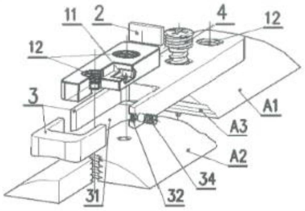
[0042] figure 1 It is a structural effect diagram of the present invention using a through-groove bone plate with a keyway insertion mosaic structure for the fixation of a single fracture of the backbone. In the figure, the right side of the fracture line A3 is the distal end of the fracture A1, and the left side of the fracture line A3 is the fracture Proximal stump A2; Bone plate 3 fixes the bone screw hole 12 on the distal stump A1 side of the fracture is a locking screw hole without a slider, the number is not limited figure 1 The two shown; the bone plate 3 that fixes the proximal end of the fracture A2 has a through groove 31, and all bone nail through holes 12 are arranged on the slider 1 in the through groove 31, figure 1 The shown slider 1 is simply a porous slider 1 (a) structure with only two bone nail through holes 12, and the bone nail through holes 12 are also locking screw holes; the shape of the slider 1 is similar to that of the described The through groove 3...

Embodiment 2

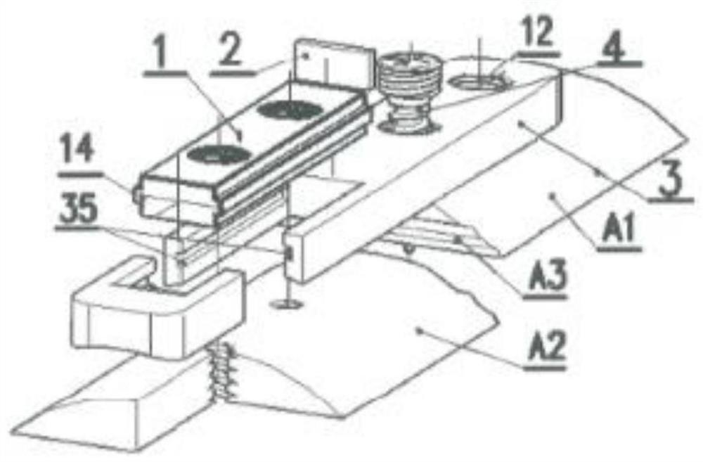
[0046] figure 2 It is a structural effect diagram of a through-groove bone plate with a mortise and riveting insertion mosaic structure for the fixation of a single bone fracture in the present invention. In the figure, except that the mosaic method of the slider 1 and the through groove 31 is changed to Except for the mortise and rivet structure of rectangular insertion, the rest are the same as in Embodiment 1; that is, the inner walls of the left and right sides of the slider 1 are respectively provided with rectangular protrusions 14, and the inner walls of the two sides of the through groove 31 are respectively provided with The matching groove band 35 of the protrusion 14 forms a matching rectangular groove-shaped tenon riveting structure for connection, and the protrusion 14 is embedded in the groove band 35 and can slide in the groove band 35 to define The slider 1 only performs axial translational movement in the through groove 31 .

[0047] The mortise and rivet st...

Embodiment 3

[0049] Figure 4 It is the structural effect diagram of the through-slot type bone plate adopting the rotating mosaic structure used for the fixation of a single bone fracture in the present invention. In the figure, except for the mosaic structure of the slider 1 and the through groove 31, the rest of the structure is the same as that of the first embodiment .

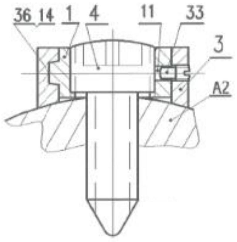
[0050] In the third embodiment, the two side walls of the slider 1 and the two inner walls of the through groove 31 are arranged as symmetrical concentric circles, and the slider 1 is embedded in the through groove 31 in a rotating manner, as Figure 5 , Figure 6 As shown; in order to facilitate the screwing of the slider 1 into the through groove 31, the edges of both sides of the through groove 31 of the bone plate 3 can be chamfered into an arc shape, so that the slider 1 can be easily screwed in In the through groove 31; second, the slider 1 can be rotated laterally with the longitudinal axis of the bone plate ...


PUM

PropertyMeasurementUnit
Thicknessaaaaaaaaaa

Abstract

The invention relates to a four-limb fixing steel plate capable of automatically converting AO rigid fixation into BO elastic fixation. The four-limb fixing steel plate comprises a bone fracture plate, a through groove / groove, a sliding block and the like, wherein the bone fracture plate is provided with screw through holes and is fixed through bone fracture nails; when a gasket is additionally arranged between the sliding block and the through groove or the groove and the bone fracture nail is fixed, rigid connection is formed among the sliding block, the bone fracture plate, the bone fracture nails and the broken bone, the whole system forms a stable rigid structure at the beginning of fixation, and the bone fracture / fixture complex is in stable static fixation. Along with the gradual degradation and absorption of the gasket in the body, the connection between the sliding block and the bone fracture plate is gradually loosened; however, the position relation between the bone fracturenails and the sliding block and the position relation between the bone fracture nails and the bone are still rigid connection, the sliding block limited by the bone fracture nails can only axially slide along the bone fracture plate under the action of external force on the bone, axial non-rigid connection is formed between the sliding block and the bone fracture plate, and fixation of the wholesystem is gradually changed into axial non-rigid dynamic fixation. Therefore, fracture healing is facilitated, and an operation of removing a steel plate is omitted.

Description

technical field [0001] The invention belongs to the field of medical devices, and in particular relates to a bone plate that can be automatically converted from rigid fixation to elastic fixation. Background technique [0002] After more than 50 years of evolution, the mainstream fracture fixation method in the world has changed from the AO theory and instruments of strong fixation to the BO theory and instruments of elastic fixation. However, from the perspective of the fracture healing process, early strong fixation can prevent the displacement of the stump and fixation failure, and provide conditions for early functional exercise; while changing to elastic fixation with relatively weak fixation strength in the middle and late stages of fracture healing can help reduce fracture damage. The stress shielding of the broken end enables the broken end of the bone to obtain axial physiological stress stimulation that is beneficial to bone healing, thereby improving the quality o...

Claims


Application Information

Patent Timeline
IPC IPC(8): A61B17/80
CPCA61B17/8028A61B17/8057A61B17/808A61B2017/00831
Inventor 董谢平李青莉艾子政边群明李京娜梅宇翔何伟义
Owner 董谢平
Learn More