Magnetic isolator based on full-symmetric coil structure
A fully symmetrical and isolator technology, applied in coils, voltage/current isolation, instruments, etc., can solve problems such as low CMTI index and inconsistent capacitance, and achieve the effect of improving CMTI index
- Summary
- Abstract
- Description
- Claims
- Application Information
AI Technical Summary
Problems solved by technology
Method used
Image
Examples
Embodiment 1
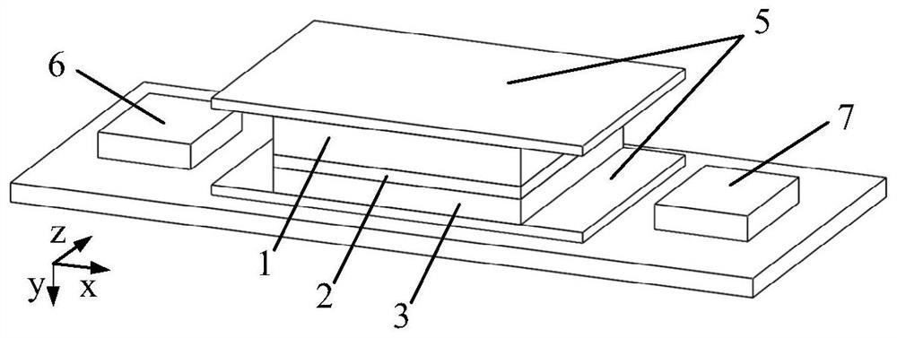
[0033] refer to figure 1 and figure 2 , a magnetic isolator based on a fully symmetrical coil structure, comprising a magnetic field generating unit 1, an isolation dielectric plate 2, a magnetic field induction unit 3 and a dielectric substrate 4 stacked sequentially from top to bottom, the upper surface of the magnetic field generating unit 1, And between the magnetic field induction unit 3 and the dielectric substrate 4, each is provided with a shielding layer 5 for absorbing external disturbance magnetic fields;
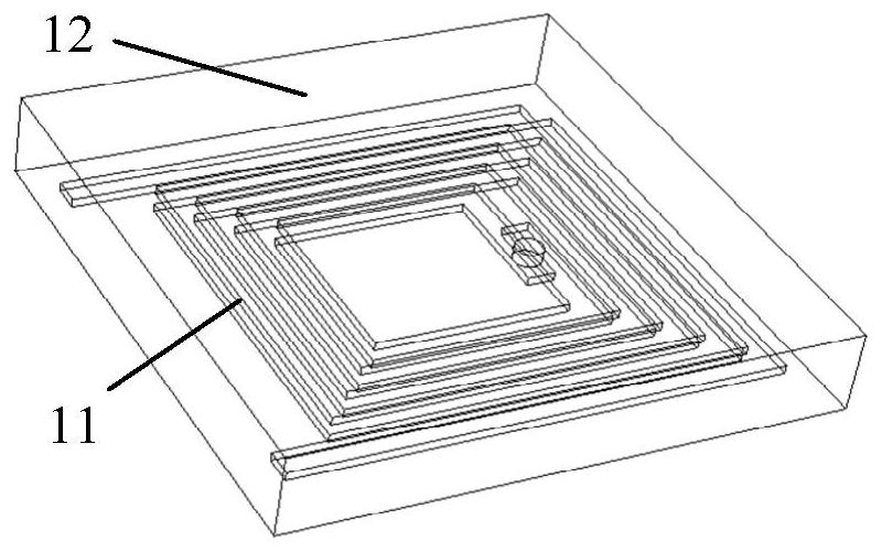
[0034] The magnetic field generating unit 1 has a structure such as image 3As shown, it includes a fully symmetrical coil structure 11 and a first dielectric body 12; the fully symmetrical coil structure 11 includes a planar helical first coil 111 and a second coil 112 arranged up and down and in the same direction of rotation, and its structure is as follows Figure 4 As shown, the first dielectric body 12 is made of silicon material or aluminum nitride mate...
Embodiment 2
[0042] refer to Figure 7 , this embodiment adds an input logic module 6 and an output logic module 7 on the basis of embodiment 1;
[0043] When the input signal is a voltage pulse signal, the input and output of the magnetic field generating unit 1 are loaded with an input logic module 6 for converting the input voltage pulse signal into a differential current pulse signal, and the input logic module 6 is placed on On the dielectric substrate 4 on the side of the input end and output end of the magnetic field generating unit 1, the signal input end 61 is connected to the input voltage pulse signal, the power supply end 62 is connected to the external power supply end, and the signal output end 63 is connected to the input end of the magnetic field generating unit 1 and output, effectively expanding the function.
[0044] The output logic module 7 includes a filter module, an amplification module, and a comparison module, and is located on the dielectric substrate 4 on the o...
PUM
 Abstract
Description
Claims
Application Information
 - R&D
- Intellectual Property
- Life Sciences
- Materials
- Tech Scout
- Unparalleled Data Quality
- Higher Quality Content
- 60% Fewer Hallucinations
Browse by: Latest US Patents, China's latest patents, Technical Efficacy Thesaurus, Application Domain, Technology Topic, Popular Technical Reports.
© 2025 PatSnap. All rights reserved.Legal|Privacy policy|Modern Slavery Act Transparency Statement|Sitemap|About US| Contact US: help@patsnap.com


