
Electronic circuit monitoring method

An electronic circuit and circuit technology, applied in multiple tester circuits, measuring electricity, measuring devices, etc., can solve the problems of dust on the multimeter, unable to adjust the angle of the multimeter, and inconvenient to use, and achieve simple monitoring process and protective effect. Good and easy to operate effect

Inactive Publication Date: 2020-09-11
HENAN UNIV OF URBAN CONSTR
View PDF10 Cites 1 Cited by
  • Summary
  • Abstract
  • Description
  • Claims
  • Application Information

AI Technical Summary

Problems solved by technology

[0002] Electronic circuit refers to a circuit composed of electronic devices and related radio components, which can display the connection control relationship inside complex electronic products in the most concise and intuitive form, so that the installation, debugging and maintenance personnel of electronic products can quickly Understand the internal structure and working principle of the entire electronic product within a short time, and then complete the corresponding work under the instruction of the electronic circuit diagram. In the actual production and maintenance work, the connection relationship, assembly relationship and working process of the electronic circuit will pass through different electronic circuits. The circuit diagram shows that a multimeter is often used in electronic circuit monitoring. However, when the current multimeter is used, the angle of the multimeter cannot be adjusted, which is not very convenient to use. After it is used up, the multimeter can be protected. Dust will affect the normal operation of the next time. It is troublesome to monitor the electronic circuit now. It cannot be intuitively obtained, and manual comparison is required. It is not worth widely popularizing and applying.

Method used


Image

  • Electronic circuit monitoring method
  • Electronic circuit monitoring method
  • Electronic circuit monitoring method

Examples


Embodiment Construction

[0024] The following will clearly and completely describe the technical solutions in the embodiments of the present invention with reference to the accompanying drawings in the embodiments of the present invention. Obviously, the described embodiments are only some, not all, embodiments of the present invention. Based on the embodiments of the present invention, all other embodiments obtained by persons of ordinary skill in the art without making creative efforts belong to the protection scope of the present invention.

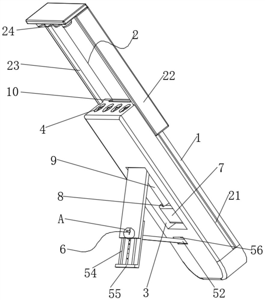
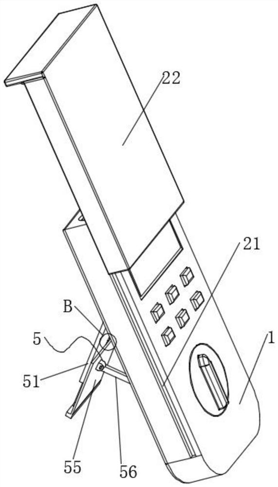
[0025] see Figure 1-5 , the present invention provides a technical solution: an electronic circuit monitoring method, comprising the following steps: Step 1, adjusting the multimeter; Step 2, monitoring the circuit; Step 3, data retrieval; Step 4, data comparison; Step 5, information output ;

[0026]In the above step 1, put the multimeter prepared, set the selection switch to the high-magnification position, short the two test leads and adjust the zero posi...


PUM


Abstract

The invention discloses an electronic circuit monitoring method. The method comprises the following steps of 1, universal meter adjustment, 2, circuit monitoring, 3, data calling, 4, data comparison and 5, information input. In the step 1, a meter pen is connected, a red meter pen is inserted into a Vomega gear, a black meter pen is inserted into a COM end, the universal meter is ensured to be normal, a gear of the universal meter is rotated, a resistance gear needs to be used for measuring the resistance value, and a gear knob is rotated to a proper resistance gear. A protection assembly is arranged, due to a protective cover and a protective plug, when the universal meter is not used, the universal meter can be well protected, the protection effect is good, and dust can be effectively prevented from entering the interior and the surface of the universal meter. An adjusting assembly is arranged, the structure is simple, the operation is convenient, and the inclination angle of the universal meter can be adjusted conveniently. The method disclosed in the invention is simple in monitoring flow, enables the measured data to be compared with the standard data, can enable a person to visually obtain a result, and improves the monitoring efficiency.

Description

technical field [0001] The invention relates to the technical field of electronic circuits, in particular to an electronic circuit monitoring method. Background technique [0002] Electronic circuit refers to a circuit composed of electronic devices and related radio components, which can display the connection control relationship inside complex electronic products in the most concise and intuitive form, so that the installation, debugging and maintenance personnel of electronic products can quickly Understand the internal structure and working principle of the entire electronic product within a short time, and then complete the corresponding work under the instruction of the electronic circuit diagram. In the actual production and maintenance work, the connection relationship, assembly relationship and working process of the electronic circuit will pass through different electronic circuits. The circuit diagram shows that a multimeter is often used in electronic circuit mo...

Claims


Application Information

Patent Timeline
Patent Type & Authority Applications(China)
IPC IPC(8): G01R15/12G01R31/01G01R1/04
CPCG01R15/125G01R31/013G01R1/04
Inventor 李慧李小敏杨帆马亮
Owner HENAN UNIV OF URBAN CONSTR
Learn More