
Connecting structure suitable for missile launcher loading

A missile launcher and connection structure technology, which is applied in the direction of the launch device, connection, and parts of the connection device, can solve the problems of low efficiency of large-diameter cables, large diameter of launch cables, and affecting loading efficiency, so as to save loading time, The effect of improving installation efficiency and improving loading efficiency

Pending Publication Date: 2020-09-11
SHANGHAI INST OF ELECTROMECHANICAL ENG
View PDF9 Cites 3 Cited by
  • Summary
  • Abstract
  • Description
  • Claims
  • Application Information

AI Technical Summary

Problems solved by technology

No matter which method is used, after the missile is loaded into the launcher, the launch cable needs to be laid one by one from the launch device to each missile. Since the missile is relatively compact and the diameter of the launch cable is large, this process takes a lot of time. Affect loading efficiency and restrict combat effectiveness
[0004] Patent document CN205980935U discloses a missile loading device, which includes a bomb-carrying guide rail, a hand drive device, a bomb-pushing trolley, a leveling support device and a vehicle frame, and the described bomb-pushing trolley is slidably installed on the bomb-carrying guide rail, and pushes The missile trolley is driven by a hand drive device installed at the end of the bomb-carrying guide rail, the vehicle frame is installed on the leveling support device, and the bomb-carrying guide rail is installed on the vehicle frame, but this design still cannot solve the problem of missile loading. The problem of low efficiency when connecting large diameter cables

Method used


Image

  • Connecting structure suitable for missile launcher loading
  • Connecting structure suitable for missile launcher loading
  • Connecting structure suitable for missile launcher loading

Examples


Embodiment Construction

[0041] The present invention will be described in detail below in conjunction with specific embodiments. The following examples will help those skilled in the art to further understand the present invention, but do not limit the present invention in any form. It should be noted that those skilled in the art can make several changes and improvements without departing from the concept of the present invention. These all belong to the protection scope of the present invention.

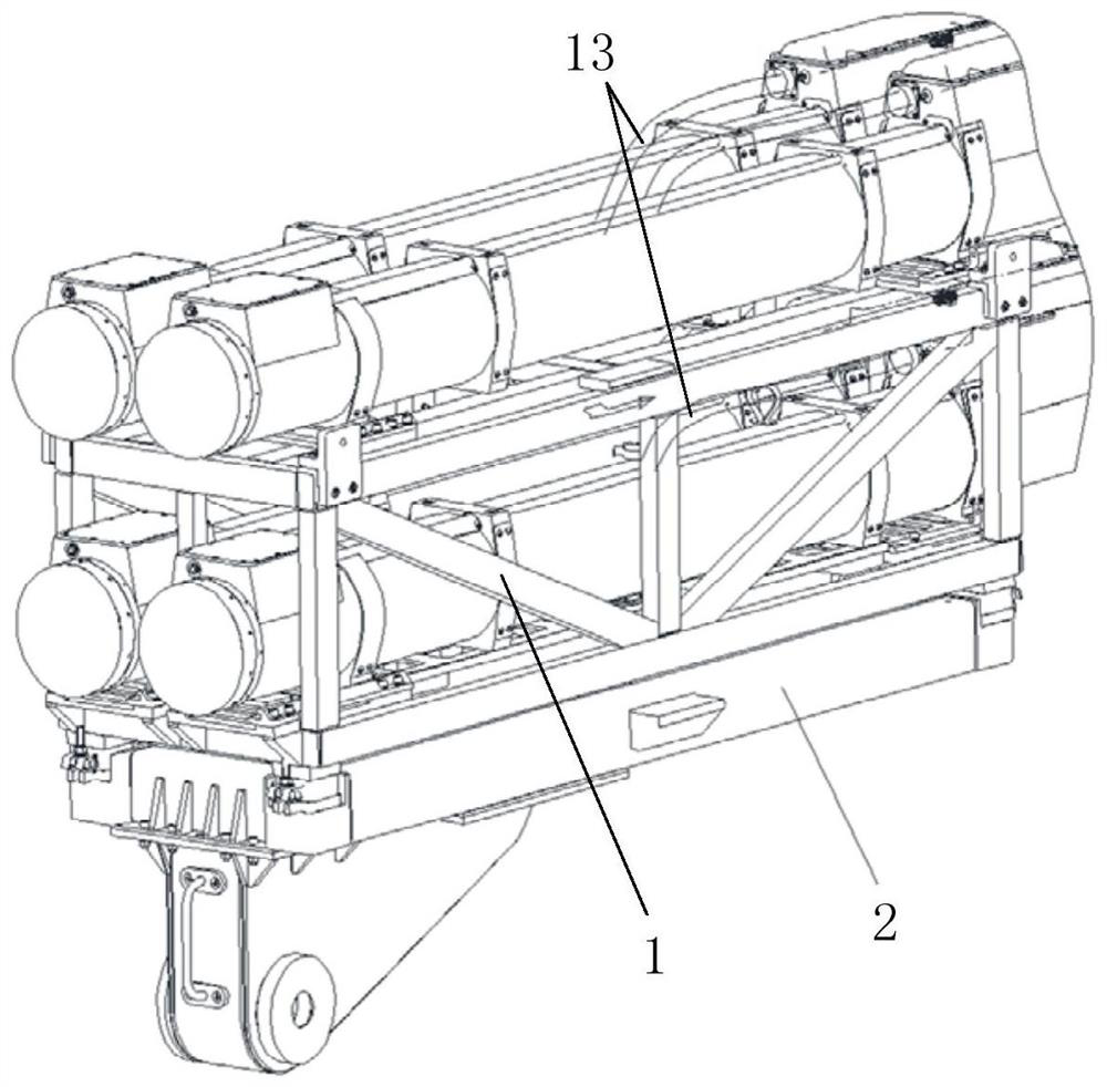
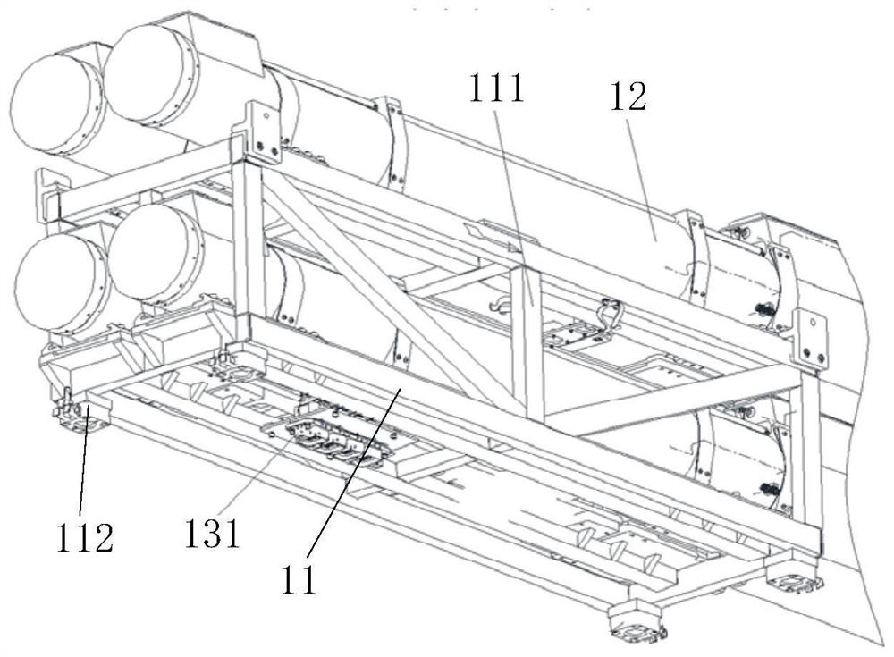
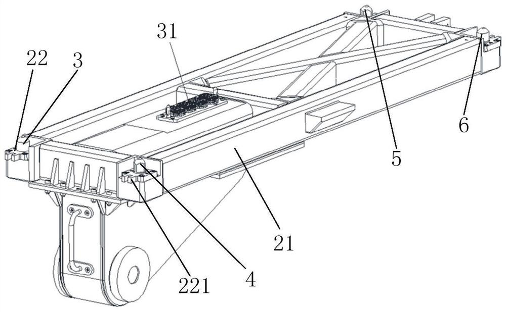
[0042] The invention provides a connection structure suitable for loading missile launchers, such as Figure 1-4 As shown, it includes a missile joint installation module 1, a missile launcher 2 and a vehicle-mounted launch control cable. The missile joint installation module 1 is provided with a joint installation rack cable 13, and the missile joint installation module 1 is installed on the missile launcher 2. In addition, the connecting rack cable 13 can be connected with the vehicle-mounted launch c...


PUM


Abstract

The invention provides a connecting structure suitable for missile launcher loading. The connecting structure comprises a missile united loading module, a missile launcher and a vehicle-bone launchingcontrol cable, wherein the missile united loading module is provided with a united loading frame cable, the united loading frame cable adopts a one-driving-four structure mode and comprises a rectangular connector plug, and the vehicle-bone launching control cable comprises a rectangular connector socket; the rectangular connector socket is arranged on the upper portion of a launcher body, and the rectangular connector plug is arranged on the lower portion of a missile united loading frame; and when the missile united loading module is arranged on the missile launcher, the rectangular connector plug can be connected into the rectangular connector socket in a matched and inserted mode, so that rapid inserting connection of a large-diameter missile launching cable is achieved. According tothe connecting structure suitable for missile launcher loading, the connection of the electrical plug is completed while a launcher structure is loaded with the united loading module, so that the loading time is saved, the loading efficiency is improved, and the reliability and the firmness of the connection are improved.

Description

technical field [0001] The invention relates to the launcher technology of a vehicle-mounted anti-aircraft missile weapon system, in particular to a structure and method for loading and connecting a missile assembly module to a missile launcher, and in particular to a connection structure suitable for loading a missile launcher. Background technique [0002] Anti-aircraft missiles refer to missiles launched by the ground, ships or submarines to intercept air targets, and are also called surface-to-air missiles in the West. Due to the high speed and high mobility of most air targets, the vast majority of anti-aircraft missiles have an axisymmetric layout. The power plant mostly uses solid rocket motors, and liquid rocket motors, ram air jet engines and rocket ramjet engines can also be used. [0003] The launcher of the vehicle-mounted air defense missile weapon system is limited by the total weight and the number of missiles loaded is limited. In order to achieve the ability...

Claims


Application Information

Patent Timeline
IPC IPC(8): F41F1/00H01R31/06H01R13/627
CPCF41F1/00H01R31/06H01R13/627
Inventor 周元春解强齐可鑫陈志清王旭烽韩锐范文晶汤日佳李颖
Owner SHANGHAI INST OF ELECTROMECHANICAL ENG
Learn More