Light-emitting device and flexible filament lamp

A technology for light-emitting devices and flexible light bars, which is applied to lighting devices, components of lighting devices, semiconductor devices of light-emitting elements, etc. Automatic assembly and other problems, to achieve the effect of solving the discontinuity of light perception, reducing production costs and improving production efficiency

Pending Publication Date: 2020-09-11
XIAMEN YANKON ENERGETIC LIGHTING CO LTD
View PDF10 Cites 1 Cited by
  • Summary
  • Abstract
  • Description
  • Claims
  • Application Information

AI Technical Summary

Problems solved by technology

[0005] The above-mentioned flexible filament lamp, first, can only emit light in the direction perpendicular to the axis of the LED filament lamp, so there is a problem of discontinuous light perception in the direction of the filament lamp axis, and it cannot emit light at multiple angles and levels, which is not conducive to improving the filament lamp. Luminous efficiency in all directions; second, it is inconvenient to attach the flexible light bar to the support assembly, and cannot realize automatic assembly

Method used


Image

  • Light-emitting device and flexible filament lamp
  • Light-emitting device and flexible filament lamp
  • Light-emitting device and flexible filament lamp

Examples


Embodiment 1

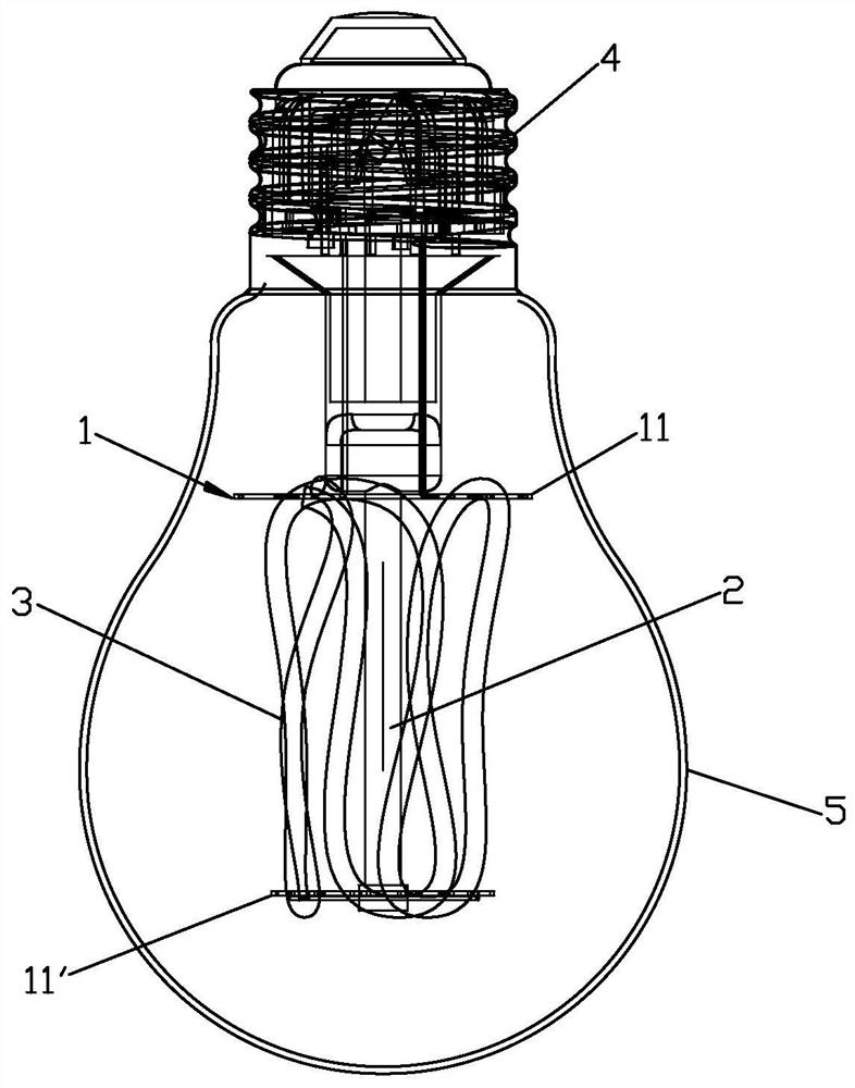
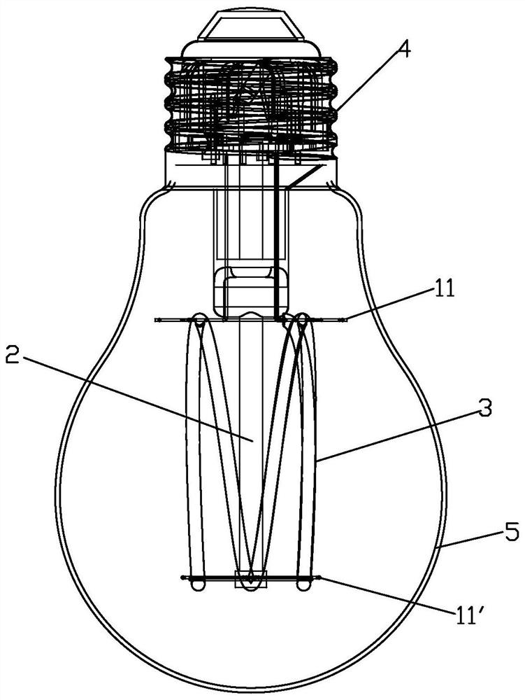
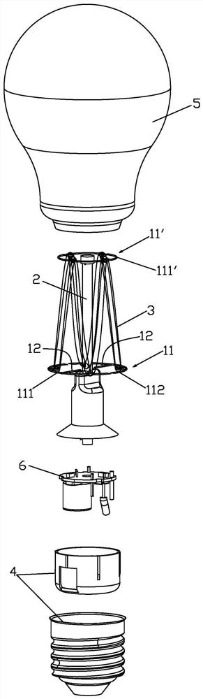
[0040] Please check Figure 1 to Figure 5 , a light emitting device comprising a support component 1 , a stem 2 supporting the support component 1 and a flexible light strip 3 . The support assembly 1 includes two surrounding frames 11, 11' sleeved outside the core column 2. The two surrounding frames 11, 11' are arranged at intervals along the core column 2 as shown in the figure. The flexible light bar 3 The two surrounding frames 11 , 11 ′ are wound alternately and cyclically at intervals to form a wavy line structure surrounding the stem 2 . The wavy line is sinusoidal or V-shaped. The flexible light bar 3 is, for example, an LED flexible light.

[0041] The two surrounding frames 11, 11' are respectively the first surrounding frame 11 and the second surrounding frame 11'. The first surrounding frame 11 includes two arc-shaped first connecting sections 111 arranged symmetrically at intervals. The two first connecting sections 111 are relatively fixedly installed on the st...

Embodiment 2

[0046] Please check Image 6 with Figure 7, it differs from Embodiment 1 in that: the first connecting section and the second connecting section are circumferentially evenly spaced and fixed with a second connecting portion convexly arranged, the second connecting portion includes a hook-shaped buckle 113, the The flexible light bar 3 is connected to the hook buckles 113 of the two surrounding frames of the support assembly 1 . The hook buckle 113 can be located on the plane of the surrounding frame 11 , or both are vertically arranged, or, the hook buckle 113 is inclined inward or outward relative to the surrounding frame 11 .

Embodiment 3

[0048] Please check Figure 8 , it differs from Embodiment 1 in that: the second connection section is a four-petal petal-shaped structure, and the end of the petal-shaped petal constitutes the third connection part 114, and the flexible light bar is connected to the two surrounding frames of the support assembly. on the third connecting portion 114 .


PUM


Abstract

The invention discloses a light-emitting device and a flexible filament lamp. The invention discloses a light-emitting device and a flexible filament lamp. The light-emitting device comprises a supporting assembly, a core column for supporting the supporting assembly and a flexible light bar, the supporting assembly comprises at least two surrounding frames which are arranged outside the core column in a sleeving mode and arranged along the core column at intervals, and the flexible light bar is connected to the surrounding frames of the supporting assembly in a winding mode and forms a wavy line structure surrounding the core column. Compared with the prior art, the light-emitting device and the flexible filament lamp have the advantages that on one hand, shaping can be achieved in a simple and low-cost mode, the assembling efficiency is greatly improved, even automatic winding assembling can be achieved, the production efficiency is greatly improved, the production cost is reduced, and on the other hand, effective light emitting can be conducted in all directions, and the light emitting efficiency of the filament lamp is greatly improved.

Description

technical field [0001] The invention relates to the technical field of lamps, in particular to a light emitting device and a flexible filament lamp. Background technique [0002] Existing flexible filament lamps are often used in various occasions because of their 360-degree lighting angle and excellent brightness. The existing flexible filament lamp structure mainly has the following types: [0003] First, the light emitting device of the flexible filament lamp includes a stem and a flexible light strip, and the flexible light strip is wound around the stem to form a spiral structure wound around the stem or suspended in a spiral structure, such as CN104465638A, CN209026537U, CN107420769A , CN108050399A. [0004] Second, the light-emitting device of the flexible filament lamp includes a stem and a plurality of flexible light bars, the plurality of filament bars are connected end to end, and the shape of the plurality of filament bars is straight or arc-shaped, such as CN1...

Claims


Application Information

Patent Timeline
IPC IPC(8): F21K9/232F21K9/237F21K9/238F21V19/00F21Y115/10
CPCF21V19/001F21K9/232F21K9/237F21K9/238F21Y2115/10
Inventor 李丽平杨夜开罗炳旺
Owner XIAMEN YANKON ENERGETIC LIGHTING CO LTD
Why Eureka
Try Eureka