Sanitation vehicle low-pressure water path with adjustable flushing width

A sanitation vehicle and waterway technology, applied in the field of sanitation vehicles, can solve problems such as the inability to meet the needs of use and the inability to effectively adjust the flushing width of sprinklers, and achieve the effect of real-time adjustable flushing width and expanded applicable scenarios

Inactive Publication Date: 2020-09-11
XUZHOU XUGONG ENVIRONMENTAL TECH CO LTD
View PDF7 Cites 0 Cited by
  • Summary
  • Abstract
  • Description
  • Claims
  • Application Information

AI Technical Summary

Problems solved by technology

When the sanitation vehicle with this structure is working, the flushing width of the sprinkler is only determined by the speed of the water pump, and since the water pump is driven by the power take-off mechanism of the chassis, it is limited by the driving requirements of the chassis. RPM operation, so the flushing width of the sprinkler cannot be effectively adjusted
When the sanitation vehicle encounters pedestrians on the side of the road or other working conditions that need to adjust the flushing width, it cannot meet the use requirements

Method used


Image

  • Sanitation vehicle low-pressure water path with adjustable flushing width
  • Sanitation vehicle low-pressure water path with adjustable flushing width

Examples


Embodiment 1

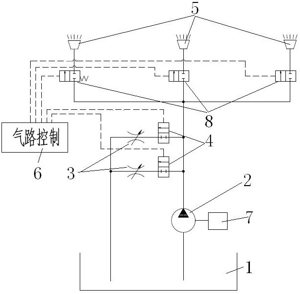
[0022] The low-pressure waterway of the sanitation vehicle with adjustable flushing width of the present invention, such as figure 1 As shown, it includes water tank 1, water pump 2, throttle valve 3, pneumatic cut-off valve 4, sprinkler 5, control air circuit 6 and connecting pipeline, etc. The power is provided by the power take-off port of the chassis 7 of the sanitation vehicle. The water outlet of the water pump 2 is connected to one or more sprinklers 5 through the connecting pipeline. The throttle valve 3 and the water channel cut-off valve 4 are connected in series, and the bypass water channel is finally connected to the water tank 1 .

[0023] A shut-off valve 8 can be arranged between the water outlet of the water pump 2 and the sprinkler 5, and the shut-off valve 8 can be controlled by automatic control methods such as air control.

[0024] When the low-pressure water circuit is in normal operation, the pneumatic cut-off valve 4 on each bypass water circuit is clo...

Embodiment 2

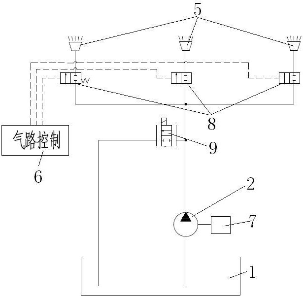
[0028] On the basis of Example 1, in other embodiments, the flow control valve 9 with electric proportional adjustment can also be used in the bypass waterway to conduct waterway on-off and flow control to realize fine control, instead of the throttle valve 3 and the pneumatic cut-off valve 4. The flow control valve with electric proportional adjustment can change the flow rate by using electric control adjustment, instead of the function realized in the case of multiple bypass water circuits in Example 1, such as figure 2 . Others are the same as in Example 1.


PUM


Abstract

The invention discloses a sanitation vehicle low-pressure water path with an adjustable flushing width. The sanitation vehicle low-pressure water path comprises a water tank, a water pump, a sprinklerand a bypass water path. The water tank is connected with a water inlet of the water pump through a connecting pipeline, and a water outlet of the water pump is connected with one or more sprinklersthrough connecting pipelines. The bypass water path capable of controlling opening and closing is arranged between the water pump water outlet and the water tank. The bypass water path is additionallyarranged at the water outlet of the water pump of the low-pressure water path; when the low-pressure water path normally operates, the bypass water path is closed, the water pump normally supplies water to the sprinklers through the pipelines, and when the water spraying pressure needs to be changed, the bypass water path can be controlled to be opened, so that the pressure of the sprinklers is changed, the real-time adjustment of the flushing width of the low-pressure water path of the sanitation vehicle is realized, and the application scene is expanded.

Description

technical field [0001] The invention relates to the field of sanitation vehicles, in particular to a low-pressure waterway system for sanitation vehicles. Background technique [0002] In the existing low-pressure water system scheme of sanitation vehicles, a centrifugal water pump is used to extract clean water from the vehicle-mounted water tank, the water outlet of the water pump is directly connected to the sprinkler through a cut-off valve, and the water pump is driven by the chassis power take-off mechanism. When the sanitation vehicle with this structure is in operation, the flushing width of the sprinkler is only determined by the rotation speed of the water pump, and since the water pump is driven by the chassis power take-off mechanism, subject to the requirements of chassis driving, the chassis engine and gearbox need to be properly operated. RPM operation, so the flush width of the sprinkler cannot be adjusted effectively. When the sanitation vehicle encounters ...

Claims


Application Information

Patent Timeline
IPC IPC(8): E01H1/10E01H3/02E03B1/04E03B7/04F17D1/14F17D3/01
CPCE01H1/10E01H3/02E03B1/04E03B7/04F17D1/14F17D3/01
Inventor 程磊单龙朱邦龙顾晓彤张二华
Owner XUZHOU XUGONG ENVIRONMENTAL TECH CO LTD
Why Eureka
Try Eureka