Guide pipe paddle supporting partition prewhirl flow guide device

A technology of diversion device and ducted propeller, which is applied in transportation and packaging, ship propulsion, ship parts, etc., can solve the problems of reduced propulsion efficiency, large flow unevenness, long distance, etc., to improve vibration and cavitation performance, The effect of improving propulsion efficiency and convenient operation

Active Publication Date: 2020-09-11
CHINA SHIP SCIENTIFIC RESEARCH CENTER (THE 702 INSTITUTE OF CHINA SHIPBUILDING INDUSTRY CORPORATION)
View PDF21 Cites 3 Cited by
  • Summary
  • Abstract
  • Description
  • Claims
  • Application Information

AI Technical Summary

Problems solved by technology

[0002] In the prior art, ducted propellers or combined propellers with ducts have a single supporting structure, which is generally composed of a flat plate without an angle of attack or a wing plate with a certain angle of attack with the incoming flow. Certain rectification and pre-rotation effects
However, when the ducted propeller is located behind the ship, under the action of multi-directional incoming flow, due to the long distance from the root of the existing support to the top in contact with the duct, and the influence of the walls at both ends, the unevenness of the flow in the radial direction behind the support is often very large. Large, it is easy to cause partial premature cavitation of the propeller, the decrease of propulsion efficiency, and the increase of bearing force, which greatly affects the hydrodynamic performance and cavitation performance of the propeller

Method used


Image

  • Guide pipe paddle supporting partition prewhirl flow guide device
  • Guide pipe paddle supporting partition prewhirl flow guide device
  • Guide pipe paddle supporting partition prewhirl flow guide device

Examples


Embodiment 1

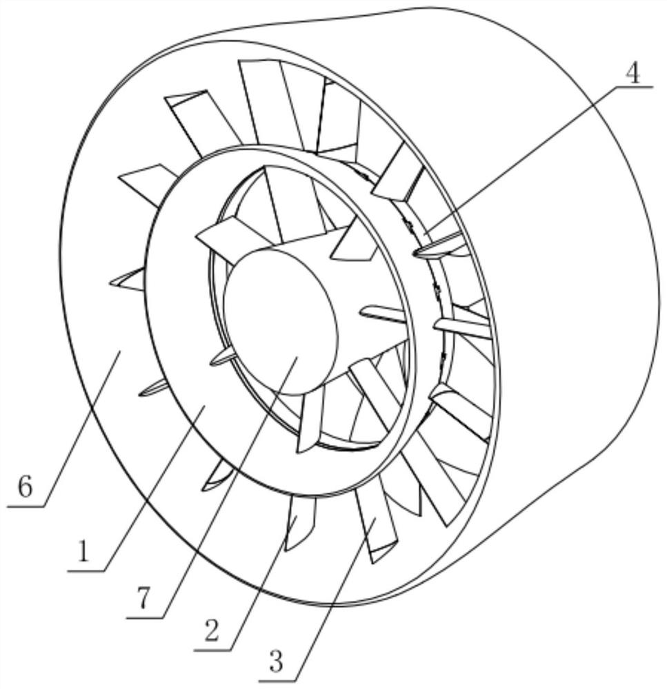
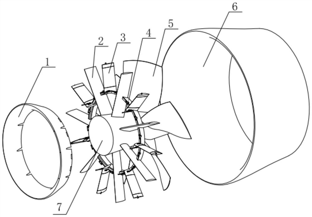
[0046] The deflector 3 is located between the deflector ring and the inner wall of the duct 6.

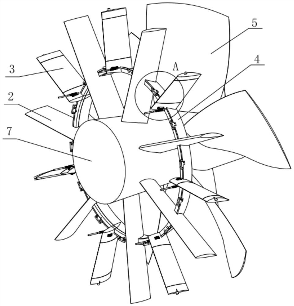
[0047] The outer guide vane 33 is fixedly mounted on the inner wall of the duct 6, and the inner guide vane 34 is embedded on the wall of the guide ring; the adjustment mechanism 9 is installed between the guide ring and the inner guide vane 34, and the worm wheel 91 is along the guide ring The tangential direction penetrates the wall surface of the inner guide vane 34, one end of the worm 92 meshes with the worm wheel 91, and the other end of the worm 92 extends to the outside of the guide ring.

[0048] The inner guide vane 34 is provided with a through groove 341 through which the worm wheel 91 penetrates. The top surface of the through groove 341 is provided with a circular hole penetrating upward, and the rotating shaft 32 at the bottom of the movable guide vane 31 is accommodated in the circular hole.

Embodiment 2

[0050] The guide vane 3 is located between the guide ring and the outer wall of the hub 7.

[0051] The inner guide vane 34 is fixedly mounted on the outer wall of the hub 7, and the outer guide vane 33 is embedded on the wall of the guide ring; the adjustment mechanism 9 is installed between the guide ring and the outer guide vane 33, and the worm wheel 91 is installed along the guide ring. The tangential direction of the ring penetrates the wall surface of the outer guide vane 33, one end of the worm 92 meshes with the worm wheel 91, and the other end of the worm 92 extends to the outside of the guide ring.

[0052] The deflector ring and the deflector 3 located inside or outside of the deflector ring all realize the division of the inside of the ducted propeller. The pre-rotation guide device, especially the adjustable deflector 3, realizes the flow field in the area through this divisional pre-rotation guide device. The flexible adjustment of uniformity not only improves the pr...


PUM


Abstract

The invention relates to a guide pipe paddle supporting partition prewhirl flow guide device. The device comprises a propeller hub, a plurality of propeller supports are uniformly distributed on the wall surface of the propeller hub along the circumferential direction; the outer ends of the propeller supports are jointly provided with a guide pipe, the end of a single propeller support is fixedlyconnected with the guide pipe, the middles of the propeller supports located between the propeller hub and the guide pipe are jointly provided with a flow guide ring in an embedded mode, the propellerhub, the flow guide ring and the guide pipe are axially concentric, and flow guide pieces are installed on the flow guide ring located between the adjacent propeller supports in the radial direction;the flow deflector comprises an inner guide vane and an outer guide vane which are located at the two ends, and a movable guide vane is rotationally installed between the outer guide vane and the inner guide vane. The movable guide vane is driven by the adjusting mechanism to deflect relative to the inner guide vane and the outer guide vane. By installing the prewhirl flow guide device, especially the adjustable flow guide pieces, flexible adjustment of the flow field uniformity is achieved, the propelling efficiency is improved, the vibration and cavitation performance is greatly improved, and the strength of the whole structure is effectively enhanced.

Description

Technical field [0001] The invention relates to the technical field of ducted propeller propellers, in particular to a ducted propeller supporting zone pre-swirl flow guiding device. Background technique [0002] In the prior art, ducted propellers or ducted combined propellers have a single support structure, generally consisting of a flat plate without an angle of attack or a wing plate with a certain angle of attack with the incoming flow. The above-mentioned structure has a single direction for incoming flow. Certain rectification and pre-spin effects. However, when the ducted propeller is located behind the ship, under the action of multi-directional flow, the distance between the root of the existing support and the top of the duct contacting the duct is long, and it is affected by the walls at both ends. The unevenness of the flow in the radial direction behind the support is often very high. Large, it is easy to cause the propeller to partially pre-cavitation, reduce the...

Claims


Application Information

Patent Timeline
IPC IPC(8): B63H5/15
CPCB63H5/15
Inventor 周斌李亮王磊李立业
Owner CHINA SHIP SCIENTIFIC RESEARCH CENTER (THE 702 INSTITUTE OF CHINA SHIPBUILDING INDUSTRY CORPORATION)
Why Eureka
Try Eureka