Electric suction negative pressure type glass cleaning tool
A negative-pressure, glass-wiping technology, applied in the field of cleaning tools, can solve problems such as difficult to control the direction, laborious use, and broken glass, so as to achieve the effects of not being easy to pinch hands, good decontamination effect, and not easy to damage the glass
- Summary
- Abstract
- Description
- Claims
- Application Information
AI Technical Summary
Problems solved by technology
Method used
Image
Examples
Embodiment 1
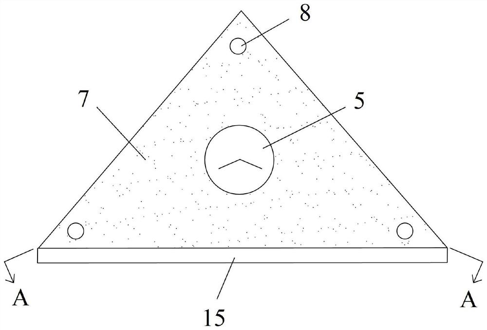
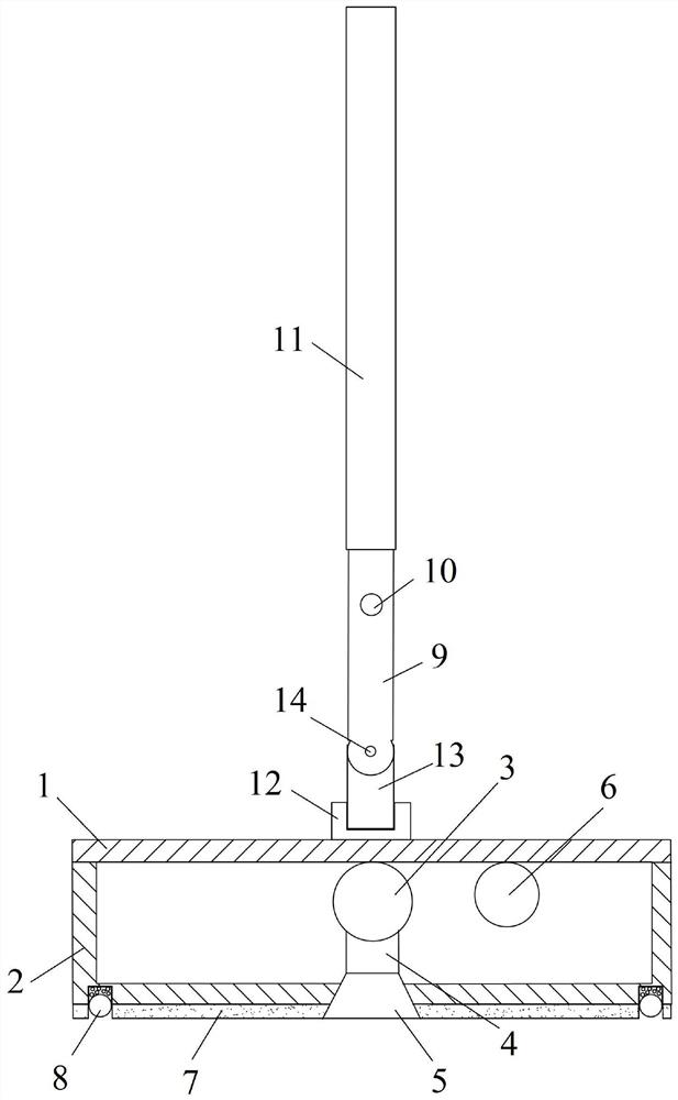
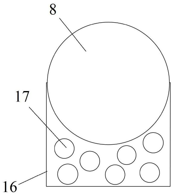
[0028] Such as figure 1 with figure 2 As shown, this embodiment provides an electric suction negative pressure glass cleaning tool, including a housing, a negative pressure pump 3, a negative pressure suction cup 5, a wiping cotton 7, a scraper strip 15, a rotating connection assembly and a handrail rod 9, and the negative pressure The pump 3 is connected with the negative pressure suction cup 5, the bottom surface of the casing is provided with a through hole, the negative pressure suction cup 5 extends to the outside of the casing through the through hole, and the outer side of the bottom surface of the casing is provided with a wiping cotton 7, and the wiping cotton 7 is arranged around the negative pressure suction cup 5, scraping The net bar 15 is arranged on one side of the bottom surface of the shell, specifically, the lower surface of the wiping cotton 7 is flush with the lower surface of the negative pressure suction cup 5 . The top surface of the casing is connecte...
Embodiment 2
[0041] Such as Figure 4 As shown, this embodiment provides an electric suction negative pressure type glass-cleaning tool. The rotating connection assembly includes a mounting table 18, a rotating connecting piece 19, a U-shaped rotating block 20 and a third pin shaft. The mounting table 18 is arranged on the upper cover 1, the mounting platform 18 is provided with a cylindrical hole, the lower end of the cylindrical hole runs through the upper cover plate 1, and the rotating connecting piece 19 is installed in the cylindrical hole. The rotating connecting piece 19 can rotate relative to the mounting platform 18, and the rotating connecting piece 19 The axial position remains unchanged, the U-shaped rotating block 20 is fixed on the upper end of the rotating connector 19, the handrail rod 9 forms a rotating connection with the U-shaped rotating block 20 through the third pin shaft, and the third pin shaft is arranged in parallel with the upper cover plate 1, U The U-shaped ro...
PUM
 Abstract
Description
Claims
Application Information
 - R&D Engineer
- R&D Manager
- IP Professional
- Industry Leading Data Capabilities
- Powerful AI technology
- Patent DNA Extraction
Browse by: Latest US Patents, China's latest patents, Technical Efficacy Thesaurus, Application Domain, Technology Topic, Popular Technical Reports.
© 2024 PatSnap. All rights reserved.Legal|Privacy policy|Modern Slavery Act Transparency Statement|Sitemap|About US| Contact US: help@patsnap.com


