
Mutual inductor winding device

A winding device and transformer technology, applied in the field of transformers, can solve problems such as uneven winding, difficult quality assurance, and low work efficiency, and achieve the effects of improving winding efficiency, reducing operating intensity, and stabilizing winding quality

Active Publication Date: 2020-09-08
北京华强诚信电器有限公司
View PDF21 Cites 0 Cited by
  • Summary
  • Abstract
  • Description
  • Claims
  • Application Information

AI Technical Summary

Problems solved by technology

[0004] Coil winding is mostly around the outside of the cylindrical body. For the winding of circular annular transformers, manual winding is often used, which has low work efficiency, high labor intensity, uneven winding, difficult quality assurance, and cannot meet mass production.

Method used


Image

  • Mutual inductor winding device
  • Mutual inductor winding device
  • Mutual inductor winding device

Examples


Embodiment Construction

[0034] The present invention will be described in further detail below in conjunction with the accompanying drawings.

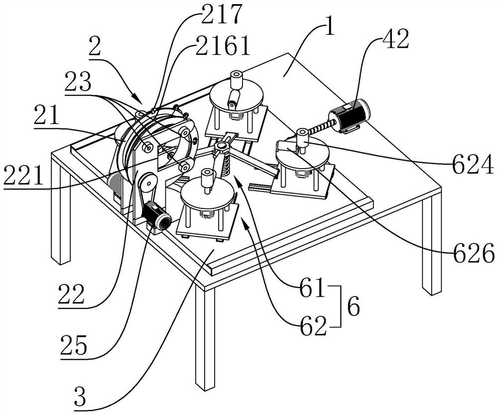
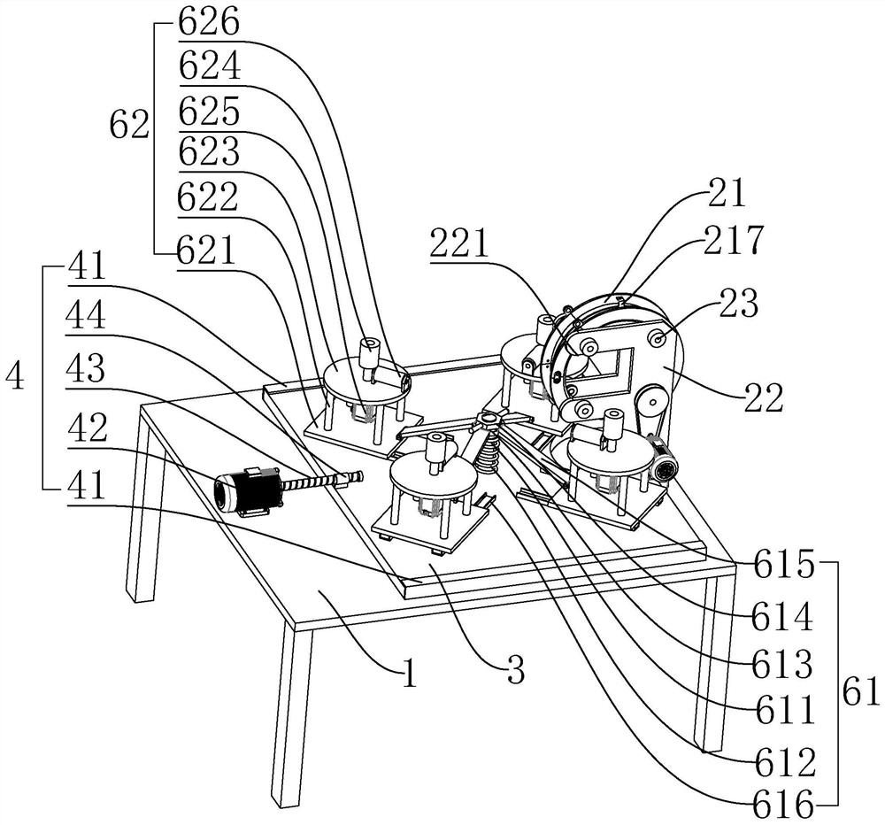
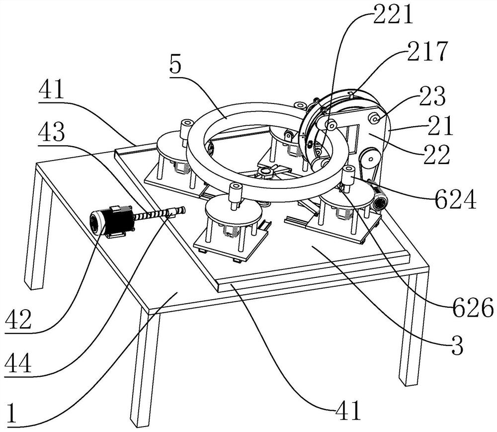
[0035] Such as Figure 1-3 As shown, a transformer winding device includes a workbench 1. A coil winding mechanism 2 for winding a coil on a transformer 5 is provided on the workbench 1. A ring for storing copper wires is rotatably installed on the coil winding mechanism 2. Shape winding reel 21; Coil winding mechanism 2 front side workbench 1 is provided with sliding plate 3, and sliding plate 3 is close to or away from coil winding mechanism 2 through sliding mechanism 4, and is provided with for supporting clip on sliding plate 3. The clamping and rotating mechanism 6 that tightens the transformer 5 and can make it rotate.

[0036] The winding reel 21 vertically passes through the transformer 5 and rotates around the transformer 5, while the transformer 5 rotates horizontally under the action of the clamping and rotating mechanism 6, and the copper wire on ...


PUM


Abstract

The invention relates to a mutual inductor winding device which comprises a workbench, a coil winding mechanism used for winding coils on a mutual inductor is arranged on the workbench, and an annularwinding disc used for storing copper wires is rotatably installed on the coil winding mechanism. A sliding plate is arranged at the position, on the front side of the coil winding mechanism, of the workbench, is close to or away from the coil winding mechanism through a sliding mechanism and is provided with a clamping rotating mechanism used for supporting and clamping the mutual inductor and enabling the mutual inductor to rotate. The efficiency of winding the coil on the mutual inductor is effectively improved, winding is uniform, the quality is stable, the operation intensity is reduced,and batch production can be met.

Description

technical field [0001] The invention relates to the technical field of transformers, in particular to a transformer winding device. Background technique [0002] During the production process of the mutual induction coil, since the mutual induction coil includes a ring composed of steel sheets, the steel sheets have multiple overlapping [0003] Together form a magnetic conductor, on which a copper wire is wound, and the copper wire needs to pass through the ring-shaped magnetic conductor for winding. [0004] Coil winding is mostly outside the cylindrical body. For the winding of circular annular transformers, manual winding is often used. The work efficiency is low, the labor intensity is high, the winding is uneven, the quality is difficult to guarantee, and it cannot meet mass production. Contents of the invention [0005] The object of the present invention is to provide a transformer winding device, which can be used for the winding of circular transformers, effecti...

Claims


Application Information

Patent Timeline
IPC IPC(8): H01F41/08
CPCH01F41/08
Inventor 刘国臧刘紫薇
Owner 北京华强诚信电器有限公司
Learn More