
Vertical microbiological detection chip

A microbiology detection and chip technology, which is applied in the measurement/testing of microorganisms, enzymology/microbiology devices, biomass post-processing, etc., can solve the problem of large pressure difference of continuous phase fluid, difficulty in distinguishing, and differences in the filling effect of micro-reaction chambers, etc. question

Active Publication Date: 2020-09-08
杭州方略生物科技有限公司
View PDF6 Cites 3 Cited by
  • Summary
  • Abstract
  • Description
  • Claims
  • Application Information

AI Technical Summary

Problems solved by technology

However, due to the resistance of the microchannel itself and the local barrier, there is a large pressure difference in the continuous phase fluid flowing between the upstream and downstream of the distribution channel, which will lead to a huge difference in the filling effect of the micro-reaction chamber at the upstream and downstream of the distribution channel.
[0005] In addition, in the process of fluorescence detection of the amplified micro-reaction chamber, the reflection and refraction of the incident excitation light often cause strong background interference; Due to the non-directional nature of the fluorescence emitted by the stimulated micro-droplets in the reaction chamber, some of the fluorescence signals between adjacent micro-wells often pass through the hole wall and are mixed with the fluorescent signals from adjacent droplets, making it difficult to distinguish The problem

Method used


Image

  • Vertical microbiological detection chip
  • Vertical microbiological detection chip
  • Vertical microbiological detection chip

Examples


Embodiment 1

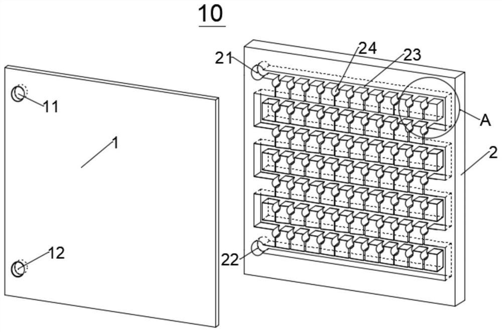
[0086] See Figure 1-2 , Provide a vertical microbial detection chip, the chip 10 is placed vertically when in use, it includes a cover sheet layer 1 and a substrate layer 2, the cover sheet layer 1 is provided with an inlet through hole 11 and an outlet through hole 12, the position of the inlet through hole 11 is higher than the outlet through hole 12; the inlet and outlet through holes 11 and the outlet through holes 12 are located at the upper and lower ends of the left side of the vertical central axis of the chip 10.

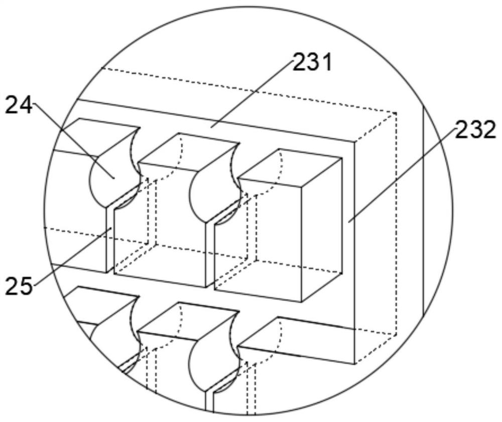
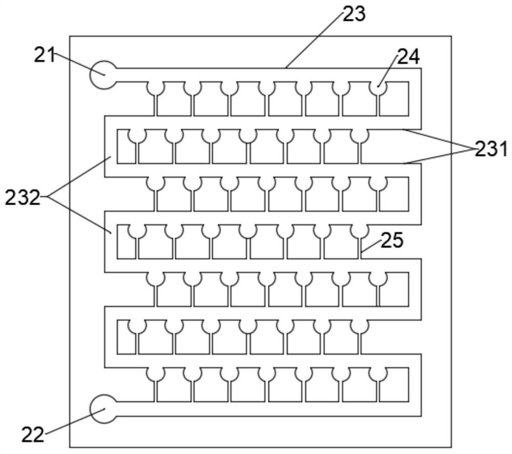
[0087] A microchannel structure is arranged on the substrate layer 2, and the microchannel structure is a non-penetrating groove. The microchannel structure includes a sample injection groove 21 and a sample discharge groove 22 respectively corresponding to the inlet through hole 11 and the outlet through hole 12 of the cover sheet layer 1, which are connected to the sample inlet groove 21 and the sample outlet groove 22, and are connected between the two The...

Embodiment 2

[0095] See Picture 11 , Provide a vertical microbial detection chip, the chip 10 is placed vertically when in use, which includes a cover sheet layer 1 having the same shape and size, a base sheet layer 2, and sandwiched between the cover sheet layer 1 and The structural layer 3 between the substrate layer 2.

[0096] See Figure 12-14 , The cover sheet layer 1 and the base sheet layer 2 have overlapping (including the same channel shape, size and position relative to the layer) non-through microchannel structure; the cover sheet layer 1 has a through inlet The hole 11 and the outlet through hole 12; the substrate layer 2 has corresponding non-through sampling groove 21 and sampling groove 22.

[0097] See Figure 15-16 , The structure layer 3 includes a portion overlapping the microchannel structure on the cover sheet layer 1 and the substrate layer 2, and the sample inlet groove 31 and the sample outlet groove corresponding to the inlet through hole 11 and the outlet through hol...

Embodiment 3

[0101] The difference from embodiment 1 or 2 is that the non-bonding sides of the cover sheet layer 1 and the base sheet layer 2 of the chip 10 are respectively coated with a polarizing coating with opposite polarization directions, and the polarizing coating completely covers the The non-adhesive side of the cover sheet layer 1 and the base sheet layer 2.


PUM


Abstract

The invention relates to a vertical microbiological detection chip. The vertical microbiological detection chip includes a conveying channel bent and extended between a chip inlet and a chip outlet, and an accommodating cavity formed in a horizontal part of the conveying channel, the bottom of the accommodating cavity is provided with a side flow channel of which the outlet is communicated with anext stage horizontally-arranged distribution channel, and a vertically-arranged chip allows an excitation light source and a fluorescence detection element to be arranged on two sides of the chip, sothat the background interference of excitation light can be completely shielded; the inlet end and the outlet end of the side flow channel are respectively communicated with the bottom of the accommodating cavity and a next stage distribution channel, so that micro-droplets can be induced under the condition of not consuming continuous phase fluid; the side flow channel can be independently arranged on a structural layer, so that the induction effect of the filled accommodating cavity on droplets is reduced or even eliminated; polarization coatings with opposite polarization directions are coated on the outer sides of a chip cover plate layer and a substrate layer, therefore, a light path between the excitation light and the fluorescence detection element is completely blocked, meanwhile,external polarization elements arranged on two sides of the chip are cooperated, a light path between a fluorescence signal emitted from the side wall of the accommodating cavity and the fluorescencedetection element can be blocked, and signal fusion between adjacent fluorescence signal points is avoided.

Description

Technical field [0001] The invention relates to a biological detection device, in particular to a vertical microbial detection chip that performs specific DNA detection of viruses, bacteria and other microorganisms through PCR reaction. Background technique [0002] The digital PCR chip based on microdroplets is one of the most advanced nucleic acid quantitative detection methods. Compared with traditional PCR technology, digital PCR will dilute the solution containing the target gene, primers, polymerase, etc. into dozens to dozens Tens of thousands of tiny, independent reactors, so that the number of nucleic acid templates in each reactor is less than or equal to one, and each reactor is subjected to traditional PCR amplification and fluorescence detection. Mark the reactor with the target gene as 1, and the reactor without the target gene as 0. According to the relative proportion and the volume of the reactor, and use the Poisson distribution to calculate the nucleic acid con...

Claims


Application Information

Patent Timeline
Patent Type & Authority Applications(China)
IPC IPC(8): B01L3/00G01N35/00C12M1/34C12M1/00
CPCB01L3/502707B01L2300/0809B01L2300/0887B01L2300/12C12Q1/6851G01N35/00029G01N2035/00158G01N2035/00237C12Q2531/113C12Q2563/159C12Q2565/629
Inventor 郑同玉
Owner 杭州方略生物科技有限公司
Learn More