
Glitch removal circuit and electronic device

一种毛刺去除、电路的技术,应用在电气元件、电压/温度变化补偿、脉冲处理等方向,能够解决产生毛刺、逻辑电路不良影响等问题

Pending Publication Date: 2020-09-04
FANUC LTD
View PDF1 Cites 0 Cited by
  • Summary
  • Abstract
  • Description
  • Claims
  • Application Information

AI Technical Summary

Problems solved by technology

In addition, glitches may also occur due to various reasons such as electrostatic discharge and radiated electromagnetic fields.
[0004] These glitches adversely affect the logic circuits of the next stage and beyond

Method used


Image

  • Glitch removal circuit and electronic device
  • Glitch removal circuit and electronic device
  • Glitch removal circuit and electronic device

Examples


Embodiment Construction

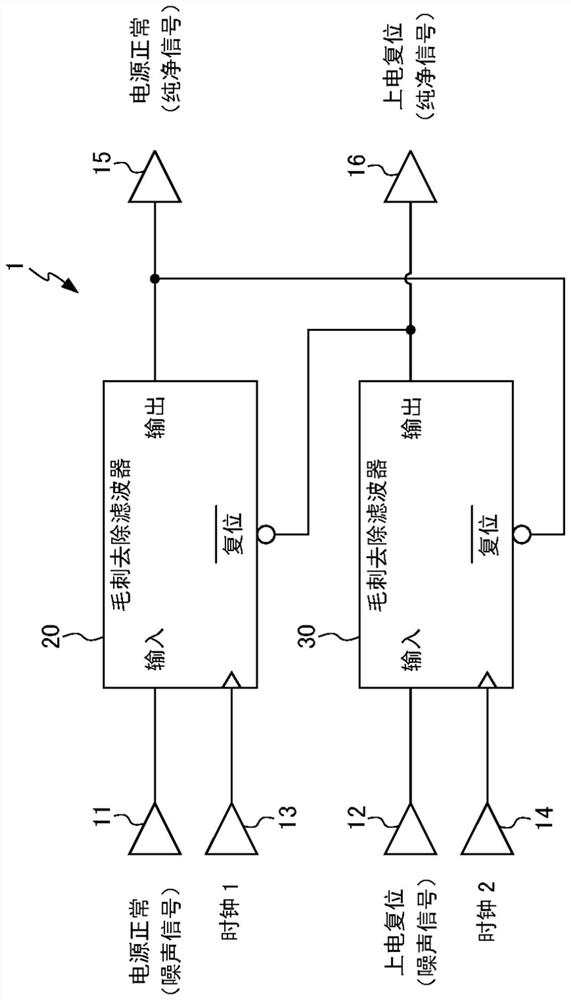
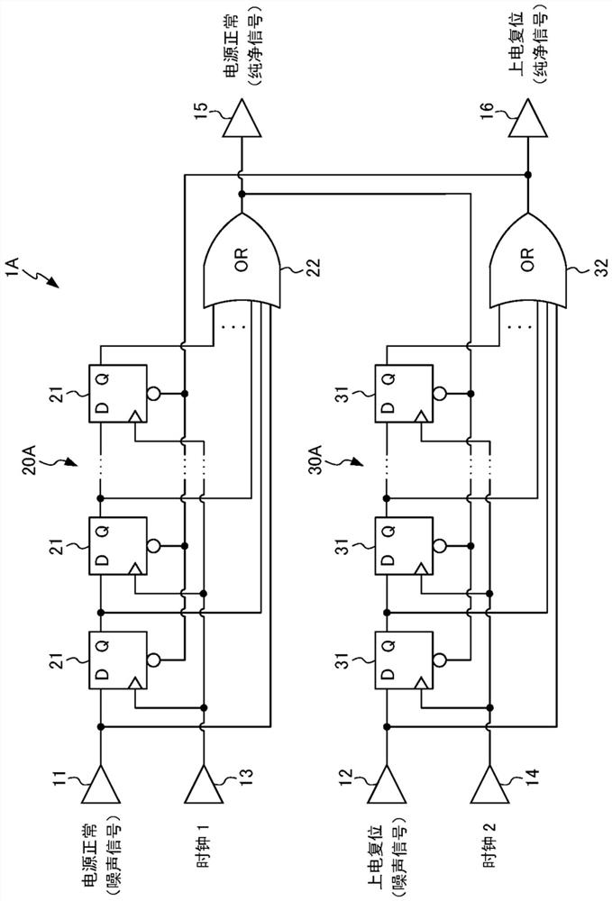
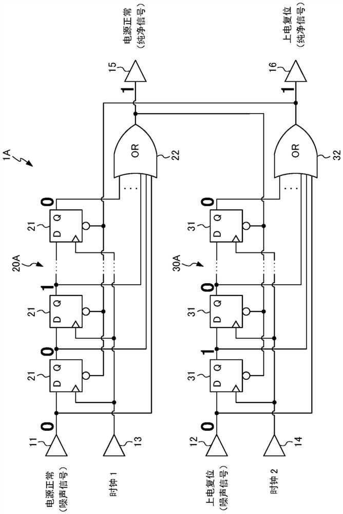
[0048] Embodiments of the present disclosure will be described below with reference to the drawings. figure 1 It is a circuit diagram showing the burr removal circuit 1 according to the first embodiment of the present disclosure. The burr removal circuit 1 is used for removing burr noise contained in the power-good (Power-good) signal and the power-on-reset (Power-on Reset) signal. In addition, in the following description, "glitch noise" may be simply referred to as "glitch" for description.

[0049] The glitch removal circuit 1 has: a first input terminal 11, which inputs the original signal of the power normal signal (a signal which may contain glitch noise); a second input terminal 12, which inputs the original signal of the power-on reset signal (which may contain glitch noise signal); the first clock terminal 13, which inputs a periodic first clock signal; the second clock terminal 14, which inputs a periodic second clock signal; the first burr removal unit 20, which w...


PUM


Abstract

The invention provides a glitch removal circuit and an electronic device. The glitch removal circuit can remove glitch noise contained in a Power-on reset signal. The glitch removal circuit removes glitch noise contained in a Power-good signal and a Power-on Reset signal, and includes: a first glitch removal unit that operates according to a first clock signal, and removes glitch noise from a Power-good signal; and a second glitch removal unit that operates according to a second clock signal, and removes glitch noise from a Power-on Reset signal, in which the first glitch removal unit is configured so as to be initialized according to an output signal of the second glitch removal unit, and the second glitch removal unit is configured so as to be initialized according to an output signal ofthe first glitch removal unit.

Description

technical field [0001] The invention relates to a deburring circuit and an electronic device. Background technique [0002] In electrical circuits, whisker-shaped pulse noise with a narrower pulse width than normal is called a glitch. In logic circuits, glitches are sometimes produced in the output when two input signals change in close proximity to each other. This is a phenomenon caused by the signal delay time of the two signals and is called racing. [0003] In addition, in an integrated circuit or the like, when a plurality of output terminals change in the same direction at the same time, glitches may occur at adjacent terminals, and this is called simultaneous switching noise. As another example, when two signals exist in parallel, when one signal changes, a glitch may be generated on the other, which is called crosstalk. In addition, burrs may also occur due to various reasons such as electrostatic discharge and radiated electromagnetic fields. [0004] These gli...

Claims


Application Information

Patent Timeline
Patent Type & Authority Applications(China)
IPC IPC(8): H03K5/07H03K5/08
CPCH03K5/07H03K5/08H03K5/1252H03K5/135H03K19/00369
Inventor 小松孝彰
Owner FANUC LTD
Learn More