Installation device of transformer for electric power engineering

A technology of electric power engineering and installation device, applied in the field of transformers, can solve the problems of unstable fixation of transformers and installation platforms, unfavorable normal operation of transformers, damage to life of transformers, etc., and achieves the effects of not easy to shake, not easy to safety accidents, and not easy to fall.

Active Publication Date: 2020-09-04
内蒙古精亿电气工程有限公司
View PDF10 Cites 2 Cited by
  • Summary
  • Abstract
  • Description
  • Claims
  • Application Information

AI Technical Summary

Problems solved by technology

[0004] The purpose of the present invention is to provide a transformer installation device for power engineering, aiming to solve the problem that the transformers in the prior art are generally installed on the pole through the installation platform. During the long-term use of the transformer, due to the internal electrical components The vibration generated during operation or the overall transformer itself under the influence of external vibration will lead to unstable fixation between the transformer and the installation platform, making it easy to slip off the pole, causing damage to the transformer or potentially affecting people's lives. The risk is not conducive to the long-term effective normal operation of the transformer

Method used


Image

  • Installation device of transformer for electric power engineering
  • Installation device of transformer for electric power engineering
  • Installation device of transformer for electric power engineering

Examples


Embodiment 1

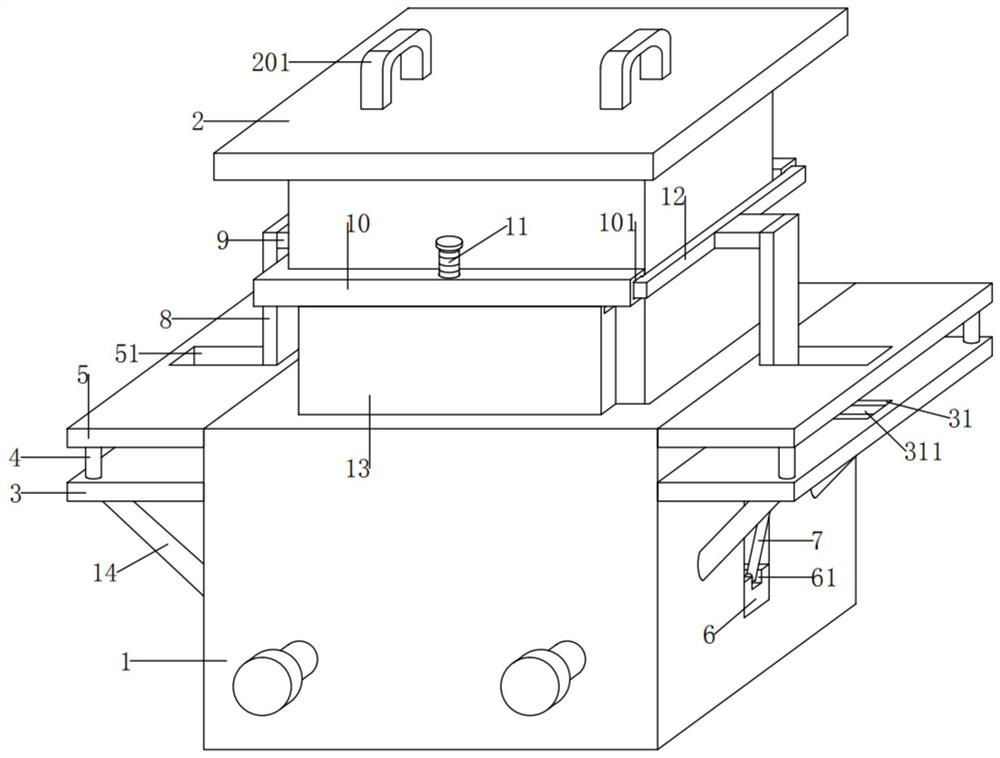
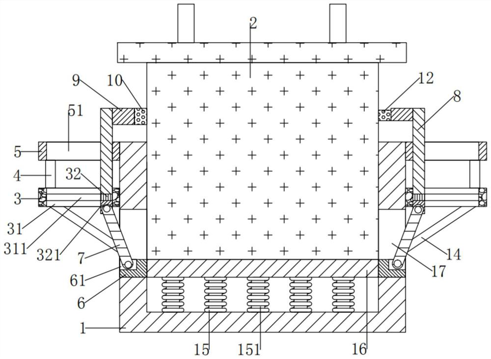
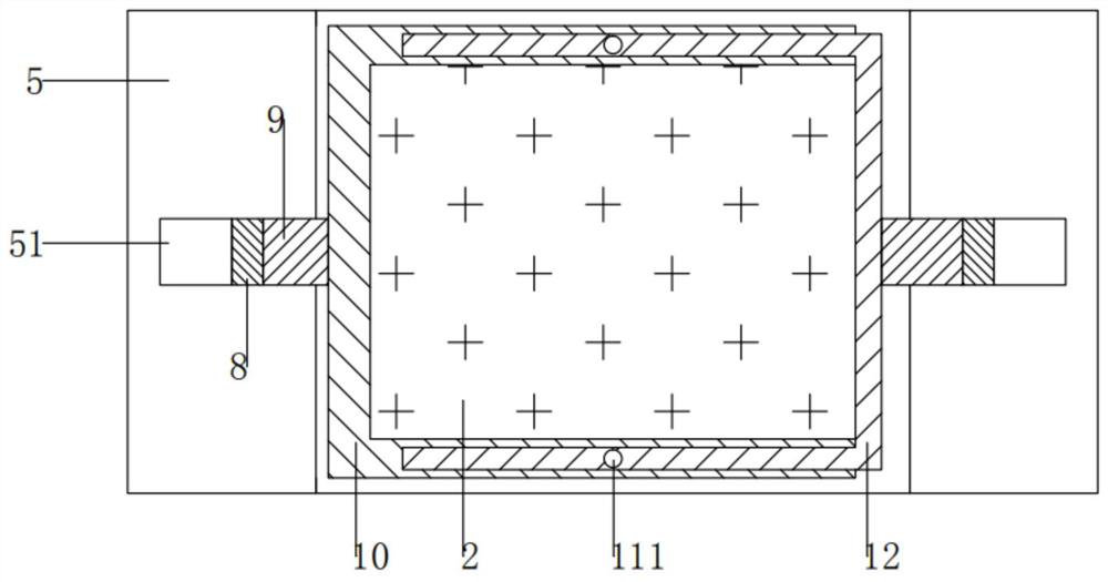
[0027] see Figure 1-5 , the present invention provides the following technical solutions:

[0028] A transformer installation device for power engineering, comprising an installation box 1, the upper end of the installation box 1 is an opening, a buckle mechanism is provided inside the installation box 1, a transformer 2 is movably inserted in the installation box 1, and the inner wall of the installation box 1 A sliding plate 16 is slidably connected between them, and the left and right ends of the installation box 1 are provided with a second chute 17, and a second sliding block 6 is slidably connected in the two second chute 17, and the two second sliding blocks 6 The adjacent ends of the sliding plate 16 are respectively fixed between the left and right ends, and the lower end of the sliding plate 16 is fixed with a plurality of first springs 15, and the lower ends of the plurality of first springs 15 are fixed with the lower inner wall of the installation box 1. , the u...


PUM


Abstract

The invention provides an installation device of a transformer for electric power engineering, and belongs to the technical field of transformers. The installation device of a transformer for electricpower engineering comprises a mounting box. The upper end of the mounting box is open. A buckling mechanism is arranged in the mounting box. A transformer is movably inserted into the mounting box. Asliding plate is slidably connected between the inner walls of the mounting box. Second sliding grooves are formed in the left and right ends of the mounting box. Second sliding blocks are slidably connected into the two second sliding grooves correspondingly. The ends, close to each other, of the two second sliding blocks are fixed to the left end and the right end of the sliding plate correspondingly, a plurality of first springs are fixed to the lower end of the sliding plate, the lower ends of the first springs are fixed to the lower inner wall of the mounting box, hinge shaft grooves areformed in the upper ends of the two second sliding blocks correspondingly, and a moving mechanism is arranged on the upper sides of the two second sliding blocks correspondingly. By means of the device, the transformer is convenient to install, stable in fixation and not prone to shaking, the transformer is not prone to falling off, and safety accidents are not prone to happening.

Description

technical field [0001] The invention belongs to the technical field of transformers, and in particular relates to a transformer installation device for power engineering. Background technique [0002] Transformer is a device that uses the principle of electromagnetic induction to change AC voltage. The main components are primary coil, secondary coil and iron core (magnetic core). The main functions are: voltage conversion, current conversion, impedance conversion, isolation, voltage stabilization (magnetic saturation transformer), etc. According to the use, it can be divided into: power transformers and special transformers (electric furnace transformers, rectifier transformers, power frequency test transformers, voltage regulators, mining transformers, audio transformers, intermediate frequency transformers, high frequency transformers, impact transformers, instrument transformers, electronic transformers , reactors, transformers, etc.). [0003] The existing transformer...

Claims


Application Information

Patent Timeline
Patent Type & Authority Applications(China)
IPC IPC(8): H01F27/06
CPCH01F27/06
Inventor 胡江廷
Owner 内蒙古精亿电气工程有限公司
Why Eureka
Try Eureka