
Flow valve, liquid rocket fuel supply system and liquid rocket

A liquid rocket and flow valve technology, applied in the field of hydraulic valves, can solve problems such as poor stability, achieve stable fluid supply, increase sealing performance, and prevent liquid leakage problems

Pending Publication Date: 2020-09-04
BEIJING XINGJI RONGYAO SPACE TECH CO LTD +2
View PDF0 Cites 2 Cited by
  • Summary
  • Abstract
  • Description
  • Claims
  • Application Information

AI Technical Summary

Problems solved by technology

[0005] Therefore, the technical problem to be solved by the present invention is to overcome the defect of poor flow supply stability of the flow valve in the liquid rocket in the prior art, thereby providing a flow valve, a liquid rocket feeding system, a liquid rocket

Method used


Image

  • Flow valve, liquid rocket fuel supply system and liquid rocket
  • Flow valve, liquid rocket fuel supply system and liquid rocket

Examples


Embodiment 1

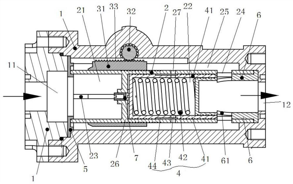
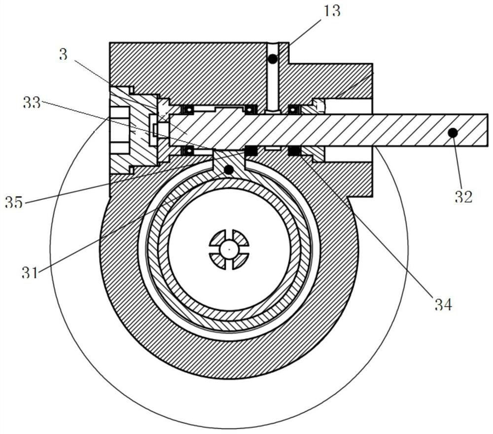
[0044] Such as Figure 1 to Figure 2 As shown, it is a flow valve provided by this embodiment, which is specifically used on a liquid rocket engine to adjust the reaction amount of liquid oxygen and methane in the liquid rocket engine, so as to realize the adjustment of the thrust of the engine.

[0045] Such as figure 1 As shown in , the flow valve includes a valve body 1, the valve body 1 is a hollow structure, and the accommodating space formed inside it is cylindrical, and the two ends of the internal space are respectively provided with an inlet 11 and an outlet 12. The medium, such as liquid oxygen or methane, flows into the flow valve in this embodiment through the inlet port 11 . In order to cooperate with the outside world, relevant joint structures can be designed at the inlet port 11 and the outlet port 12 to realize the convenience of connection.

[0046] The valve body 1 is embedded with a valve sleeve 2, which is also a hollow structure, specifically a thin-wal...

Embodiment 2

[0067] This embodiment provides a liquid rocket feeding system, including the above-mentioned flow valve, which has all the technical advantages of the flow valve in the above-mentioned embodiment 1, and will not be repeated here.

[0068] The liquid rocket feeding system includes a fuel supply pipeline and a catalyst supply pipeline, and a flow valve is installed on the above pipeline to control the flow supplied by the fuel supply pipeline and the catalyst supply pipeline to the combustion chamber of the engine, so as to ensure that the engine generates thrust stability.

Embodiment 3

[0070] This embodiment provides a liquid rocket, including the liquid rocket feeding system in Embodiment 2 above, and has all its technical advantages, which will not be repeated here.


PUM


Abstract

The invention relates to the technical field of hydraulic valves, in particular to a flow valve, a liquid rocket fuel supply system and a liquid rocket. The flow valve comprises a throttling chamber and a pressure stabilizing chamber, fluid flowing from an inflow port achieves a throttling function under the action of a first throttling opening in the throttling chamber, and the pressure of the fluid on the front and rear portions of the first throttling opening changes to guarantee that the pressure difference between the front and rear portions of the first throttling opening is stable. Thepressure stabilizing chamber is formed in the flow valve, when the pressure difference of the front and rear portions of the first throttling opening changes, an elastic part in the pressure stabilizing chamber senses the pressure change and drives a second adjusting part to move, the moving second adjusting part controls the opening degree of a second throttling opening, the second throttling opening communicates with an outflow port, and the opening degree of the second throttling opening is adjusted to adjust the pressure in a cavity behind the first throttling opening, so that it is ensured that the pressure difference of the front and rear portions of the first throttling opening is stable, under the condition that the pressure difference is stable, the flow stability of liquid flowing through the flow valve can be ensured, and therefore the stability of fluid supply is ensured.

Description

technical field [0001] The invention relates to the technical field of hydraulic valves, in particular to a flow valve, a liquid rocket feeding system and a liquid rocket. Background technique [0002] With the intensification of commercial aerospace competition, the requirements for the reliability and economy of launch vehicle engines are also getting higher and higher. In order to reduce the cost of a single launch and improve commercial competitiveness, the rocket needs to be reusable. During the recovery process of the rocket, the thrust of the engine must be precisely adjusted to ensure that the launch vehicle can land smoothly and be reused. [0003] The thrust adjustment function of the reusable cryogenic liquid oxygen methane engine is realized by the regulating valve arranged in the medium pipeline, and the regulating valve is the core component to realize the thrust adjustment of the rocket engine. The regulating valve adjusts the flow and pressure of the flowin...

Claims


Application Information

Patent Timeline
Patent Type & Authority Applications(China)
IPC IPC(8): F02K9/58
CPCF02K9/58
Inventor 彭小波魏一张玺
Owner BEIJING XINGJI RONGYAO SPACE TECH CO LTD
Learn More