
Rail transit communication signal processing device and method

A technology for communication signals and rail transit, applied in the field of rail transit, can solve the problems of misreading signal lights, increasing traffic accidents, inconvenience, etc., and achieve the effect of easy maintenance and replacement, convenient operation, and firm fixation

Inactive Publication Date: 2020-09-04
ANHUI UNIV OF SCI & TECH
View PDF15 Cites 2 Cited by
  • Summary
  • Abstract
  • Description
  • Claims
  • Application Information

AI Technical Summary

Problems solved by technology

[0003] In practical applications, after the rail transit arrives at the station, the stop time is determined according to the signal light. However, generally only a single signal light device is installed at a single stop, but there are multiple tracks next to the station. Drivers have different observation angles for the signal lights after entering the station. It is easy to cause sunlight to cause misreading of signal lights, which increases the possibility of traffic accidents
[0004] At the same time, most of the existing signal lights are fixed. When damage occurs, the worker master needs to use tools to climb up to repair it, but climbing up increases the possibility of dangerous accidents and threatens the life safety of the worker master to a certain extent. Inconvenience for practical application

Method used


Image

  • Rail transit communication signal processing device and method
  • Rail transit communication signal processing device and method
  • Rail transit communication signal processing device and method

Examples


Embodiment Construction

[0048] The following will clearly and completely describe the technical solutions in the embodiments of the present invention with reference to the accompanying drawings in the embodiments of the present invention. Obviously, the described embodiments are only some, not all, embodiments of the present invention. Based on the embodiments of the present invention, all other embodiments obtained by persons of ordinary skill in the art without creative efforts fall within the protection scope of the present invention.

[0049] In describing the present invention, it is to be understood that the terms "opening", "upper", "lower", "thickness", "top", "middle", "length", "inner", "surrounding" etc. Indicating orientation or positional relationship is only for the convenience of describing the present invention and simplifying the description, and does not indicate or imply that the components or elements referred to must have a specific orientation, be constructed and operated in a sp...


PUM


Abstract

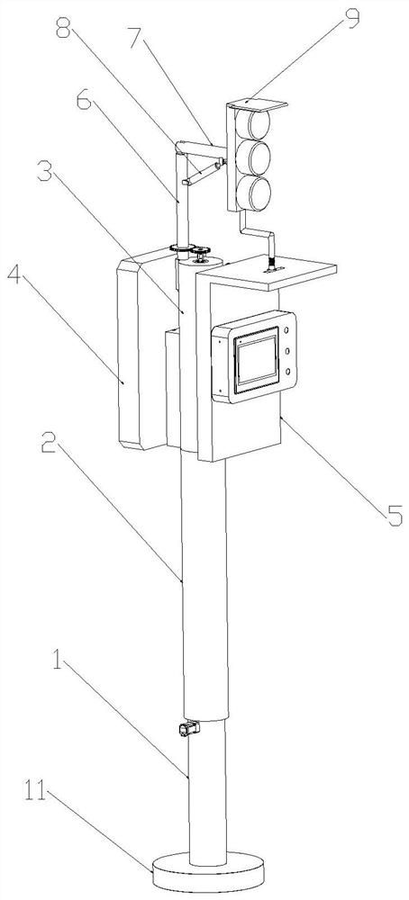
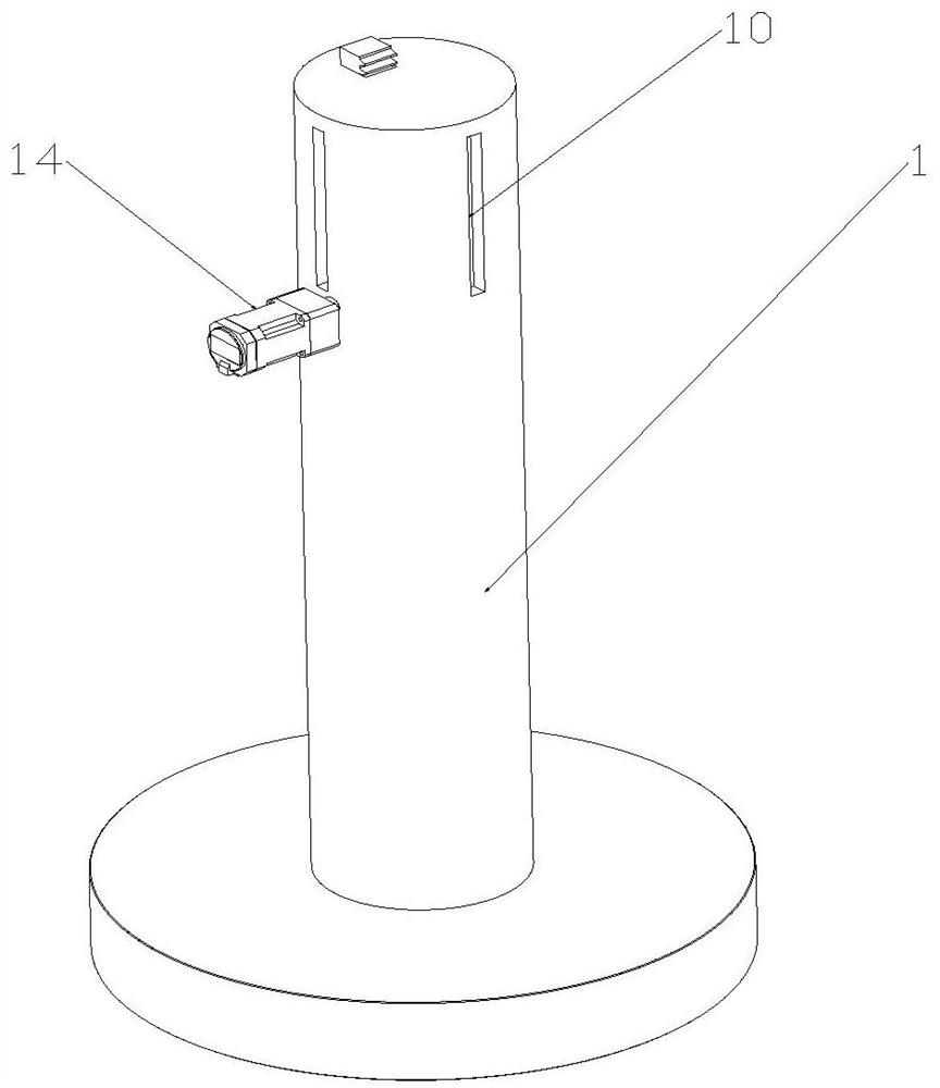
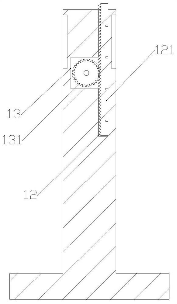
The invention discloses a rail transit communication signal processing device and method. The device is provided with a first motor, a second motor and an electric push rod, wherein the first motor isdriven to drive a first gear to rotate, the first gear drives a rack to slide up and down in a first rectangular groove, and the rack drives a lifting rod to move up and down to further drive a signal lamp to move to a proper position; the second motor is driven, two gears rotate to drive a rotating rod and a supporting rod to rotate, and the proper rotating position of the signal lamp is adjusted; the electric push rod is driven, the supporting rod is driven to rotate, a telescopic spring deforms while the supporting rod rotates, the supporting rod rotates to adjust the emitting angle of thesignal lamp, the signal lamp can be located at the most appropriate angle, a driver can observe signals at the most comfortable observation angle, and the possibility of accidents is reduced. Meanwhile, a bearing rod is clamped through the elastic force of the spring, the bearing rod is convenient to detach, the signal lamp is convenient to maintain and replace, the fixation is firm, and the disassembly is convenient.

Description

technical field [0001] The invention relates to the field of rail transit, in particular to a rail transit communication signal processing device and method. Background technique [0002] Rail transit refers to a type of vehicle or transportation system that operating vehicles need to run on a specific track. The most typical rail transit is a railway system composed of traditional trains and standard railways. With the diversified development of train and railway technology, more and more types of rail transit have emerged, not only in long-distance land transportation, but also in short- and medium-distance urban public transportation. Rail transit has the characteristics of large transportation volume, fast speed, safety, punctuality, environmental protection, energy saving and land use. In rail transit, rail traffic signal lights are an important part of rail traffic. Reasonable design of rail traffic signal lights can improve traffic capacity and reduce the frequency o...

Claims


Application Information

Patent Timeline
Patent Type & Authority Applications(China)
IPC IPC(8): B61L5/18H02K7/06H02K7/116H02S20/00
CPCB61L5/18H02K7/06H02K7/116H02S20/00Y02E10/50
Inventor 王智
Owner ANHUI UNIV OF SCI & TECH
Learn More