
Hybrid power system and control method

A hybrid power system and control method technology, applied in the automotive field, can solve problems such as poor adaptability, increased space ratio of hybrid power system, and low work efficiency of power sources, so as to reduce space ratio, improve work efficiency, and enhance adaptability sexual effect

Active Publication Date: 2020-09-04
CHERY AUTOMOBILE CO LTD
View PDF9 Cites 2 Cited by
  • Summary
  • Abstract
  • Description
  • Claims
  • Application Information

AI Technical Summary

Problems solved by technology

[0004] However, in order to realize multi-gear shifting in related technologies, multiple sets of gear trains need to be set in the manual transmission, which will undoubtedly increase the space ratio of the hybrid system; and for automatic transmissions, the power source is usually placed in the planetary gear train. A certain part of the planetary gear train is fixedly connected. When a certain part is used as the active part in the planetary gear train, at most two gears can be changed, but multi-gear (such as 4 gears) cannot be switched.
Therefore, the hybrid power system in the related art has poor adaptability to switch different gears according to different working conditions, which makes the working efficiency of the power source low.

Method used


Image

  • Hybrid power system and control method
  • Hybrid power system and control method
  • Hybrid power system and control method

Examples


Embodiment Construction

[0036] In order to make the purpose, technical solution and advantages of the present disclosure clearer, the implementation manners of the present disclosure will be further described in detail below in conjunction with the accompanying drawings.

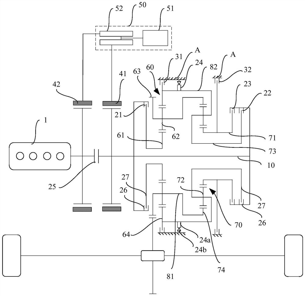
[0037] figure 1 It is a schematic structural diagram of a hybrid power system provided by an embodiment of the present disclosure. Such as figure 1 As shown, the hybrid system includes: an engine 1, a main shaft 10, a first clutch 21, a second clutch 22, a third clutch 23, a one-way clutch 24, a first planetary gear train 60, a second planetary gear train 70, a A connection cylinder 81 , a second connection cylinder 82 , the first brake 31 , the second brake 32 , the first motor 41 and the power supply assembly 50 .

[0038] Such as figure 1 As shown, the output shaft of the engine 1 is coaxially connected with the main shaft 10 , the rotor of the first motor 41 is coaxially connected with the main shaft 10 , and the first plane...


PUM


Abstract

The invention provides a hybrid power system and a control method. The system comprises an engine, a main shaft, a first clutch, a second clutch, a third clutch, a fourth clutch, a first planetary gear train, a second planetary gear train, a first connecting cylinder, a second connecting cylinder, a first brake, a second brake, a first motor and a power supply assembly, wherein an output shaft ofthe engine is coaxially connected with the main shaft; a rotor of the first motor is coaxially connected with the main shaft; the first connecting cylinder is connected with a first planet carrier anda second gear ring; the second connecting cylinder is connected with a first gear ring and a second planet carrier; the first planet carrier is in transmission connection with wheels; the first clutch is connected with the main shaft and a first center wheel; the second clutch is connected with the main shaft and the second planet carrier; the third clutch is connected with the main shaft and a second center wheel; the fourth clutch is located on the second connecting cylinder; the first brake can brake the first gear ring; and the second brake can brake the second center wheel. Multi-gear switching of the hybrid power system can be achieved, and the adaptability of the system is enhanced.

Description

technical field [0001] The present disclosure relates to the technical field of automobiles, in particular to a hybrid power system and a control method. Background technique [0002] As a fast-paced and efficient means of transportation in life, the number of vehicles has increased year by year in recent years. Most traditional vehicles use fossil fuels (such as gasoline, diesel, etc.) to power the engine, and the exhaust gas will pollute the environment, which does not meet the requirements of energy saving and environmental protection. Therefore, it is necessary to use non-polluting new energy sources (such as electric energy) to replace fossil fuels to provide power for vehicles. At present, there are hybrid electric vehicles that use new energy and fossil fuels as energy sources. Hybrid electric vehicles can greatly improve the power and fuel economy of the vehicle and reduce emissions. [0003] The transmission mechanism in the hybrid system of the hybrid electric ve...

Claims


Application Information

Patent Timeline
Patent Type & Authority Applications(China)
IPC IPC(8): B60K6/36B60K6/365B60K6/38B60K6/387
CPCB60K6/36B60K6/365B60K6/38B60K6/387B60K2006/381
Inventor 张恒先耿丽珍顾存行李亚南
Owner CHERY AUTOMOBILE CO LTD
Learn More