Car lock locking mechanism

A car, the other side of the technology, applied in the field of car locks and locking mechanisms, can solve the problems of poor user comfort, loud noise, and poor sense of the user, achieving small space ratio, fewer parts, and improved use The effect of longevity

Active Publication Date: 2017-12-15
YANTAI TRICIRCLE LOCK INDUSTRY GROUP CO LTD
View PDF19 Cites 1 Cited by
  • Summary
  • Abstract
  • Description
  • Claims
  • Application Information

AI Technical Summary

Problems solved by technology

[0002] At present, the structure of the traditional car lock usually uses the engagement between the clamp and the stop claw to realize the function of locking and opening. When the stop claw is opened, that is, when the stop claw and the clamp are disengaged, the door will The force on the clamping plate, that is, the force of the door panel is released instantly, making a loud noise, which gives the user a bad impression; at the same time, to open the car lock, it is necessary to overcome the friction force when the locking claw and the clamping plate are engaged, and this frictional force It will increase with the increase of the door sealing force, and it will also increase under the influence of dust as the use time goes by, causing users to experience poor comfort

Method used


Image

  • Car lock locking mechanism
  • Car lock locking mechanism
  • Car lock locking mechanism

Examples


Embodiment 1

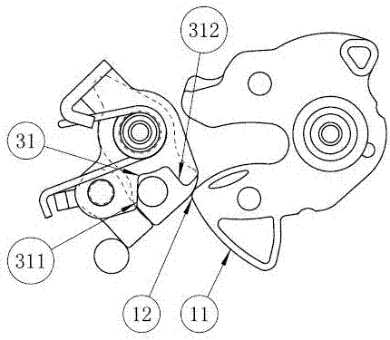
[0024] A locking mechanism for an automobile, comprising a bottom plate 7 with a lock opening, and a first rotating shaft A, a second rotating shaft B, a third rotating shaft C and a blocking block 5 arranged at a predetermined position of the bottom plate 7; wherein the first rotating shaft A rotary clamp 1 is installed on a rotating shaft A through a clamp torsion spring, an opening arm 3 and a stop pawl 2 are installed on the second rotating shaft B at the same time, a blocking arm 4 is installed on the third rotating shaft C and the blocking arm 4 Located between the stop pawl 2 and the blocking block 5 , one end of the torsion spring 6 of the stop pawl is fixed to abut against the protruding portion 43 of the blocking arm 4 .

[0025] In the above arrangement of this embodiment, the rivet is used as the rotating shaft to be riveted on the bottom plate 7, and other methods can also be used, which are not listed one by one. The characteristic is that the riveting shaft and t...


PUM


Abstract

The invention relates to a car lock locking mechanism. The mechanism comprises a rotating clamping plate (1) and a locking claw (2) which are rotatably arranged on a first rotating shaft (A) and a second rotating shaft (B) correspondingly and are matched with each other to achieve two states of locking and unlocking. The locking mechanism is characterized in that the engaging face outline (21) of the clamping plate (1) and the locking claw (2) is an eccentric arc face, the other side of the locking claw (2) is provided with a component force blocking locking mechanism which can slide firstly and then rotate; through the eccentric design of the engaging portion of the locking claw, force can be dispersed, through the component force blocking mechanism, action force can be further dissipated, releasing force instantly generated when engagement of the locking claw and the rotating clamping plate is released is effectively reduced, the noise is lowered, vibration is buffered, the service life of the lock body can be prolonged, and the user operation comfort is greatly improved.

Description

technical field [0001] The invention relates to an automobile lock locking mechanism, which belongs to the technical field of automobile lock structures. Background technique [0002] At present, the structure of the traditional car lock usually uses the engagement between the clamp and the stop claw to realize the function of locking and opening. When the stop claw is opened, that is, when the stop claw and the clamp are disengaged, the door will The force on the clamping plate, that is, the force of the door panel is released instantly, making a loud noise, which gives the user a bad impression; at the same time, to open the car lock, it is necessary to overcome the friction force when the locking claw and the clamping plate are engaged, and this frictional force It will increase with the increase of the door sealing force, and will also increase under the influence of dust as the use time goes on, causing users to feel uncomfortable in use. Contents of the invention...

Claims


Application Information

Patent Timeline
Patent Type & Authority Applications(China)
IPC IPC(8): E05B85/00E05B77/36
CPCE05B77/36E05B85/00
Inventor 林振庆张振海张锡祥张宗明张鹏飞杨秀峰王建炜柳洪贞孙振江李春杰高魁发郑海兵王文杨宗政
Owner YANTAI TRICIRCLE LOCK INDUSTRY GROUP CO LTD
Why Eureka
Try Eureka