A device for punching holes in concrete walls

A drilling device and concrete technology, applied in the direction of working accessories, manufacturing tools, stone processing tools, etc., can solve the problems of irregular orbit of electric drill, cumbersome and inconvenient operation process, and the opening of round holes is not a perfect circle, etc., so as to simplify drilling Operation process, avoiding irregular openings, and optimizing the effect of linkage structure

Active Publication Date: 2022-03-08
淄博聚德建筑安装有限公司
View PDF5 Cites 0 Cited by
  • Summary
  • Abstract
  • Description
  • Claims
  • Application Information

AI Technical Summary

Problems solved by technology

[0004] The purpose of the present invention is to provide a concrete wall punching device to solve the problem that when opening a large-diameter round hole in the above-mentioned background technology, the worker needs to manually rotate and adjust the drilling position of the electric drill on the wall for many times, so that the electric drill can Circumferential drilling, the operation process is cumbersome and inconvenient, and the manual adjustment of the electric drill's orbit is irregular, and the inside and outside will be uneven, resulting in a round hole that is not a perfect circle, and the worker usually needs to stand and push the electric drill with his hands when drilling, which consumes a lot of physical strength , Poor comfort when standing for a long time, easy to fatigue

Method used


Image

  • A device for punching holes in concrete walls
  • A device for punching holes in concrete walls
  • A device for punching holes in concrete walls

Examples


Embodiment 1

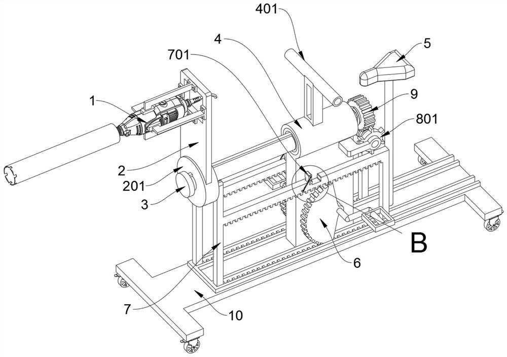
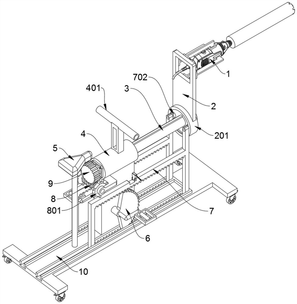
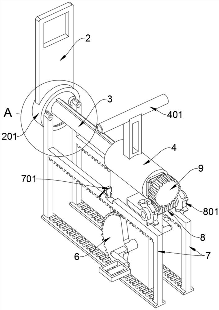
[0030] see Figure 1 to Figure 6 and Figure 8 , an embodiment provided by the present invention: a concrete wall punching device, including a mounting plate 2, a supporting shaft 3, a positioning sleeve 4, a push frame 7 and a base 10, the top end of the mounting plate 2 faces upwards An electric drill 1 is installed in the front lock; the mounting plate 2 includes a swivel 201 and an annular baffle 202, and a swivel 201 is welded and fixed at the bottom of the mounting plate 2, and the swivel 201 is slipped on the supporting shaft 3 and connected by a key transmission, and the rear side of the swivel 201 is welded with an annular baffle 202, through the swivel 201, the mounting plate 2 can drive the electric drill 1 to slide back and forth along the supporting shaft 3 for drilling; the second half of the supporting shaft 3 rotates and wears On the positioning sleeve 4, a worm gear 9 is set on the rear end of the supporting shaft 3; a vehicle seat 5 is installed on the upper...

Embodiment 2

[0033] On the basis of Example 1, please refer to Figure 4 , Figure 7 and Figure 9 , an embodiment provided by the present invention: a concrete wall punching device, which also includes a push frame 7, and the two push frames 7 are placed in two T-shaped positions on the base 10 correspondingly sliding left and right. In the chute, the push frame 7 includes a top block 701 and a guide wheel 702, and the middle section at the top of the two push frame 7 is provided with a placement groove, and the two push blocks 701 are erected on the two sides with respect to the spring pull rotation. Place in the slot; the tops of the two push frame 7 front side vertical struts are all rotatably equipped with a guide wheel 702.

[0034] Further, the inner sides of the upper and lower side bars of the two pushing frames 7 protrude to support a row of positioning teeth, and the two bevel gears 6 can alternately rotate and mesh corresponding to the upper and lower rows of positioning teet...


PUM


Abstract

The invention discloses a perforating device for concrete walls, relates to the technical field of perforating equipment, and solves the problem that the existing perforating device, manually adjusting the surrounding trajectory of an electric drill, is irregular, and the inside and outside are staggered, resulting in that the opening of a round hole is not a perfect circle. And when drilling, workers generally need to stand and push the electric drill with their hands, which is a serious problem of physical exertion. A concrete wall drilling device, comprising a mounting plate, a support shaft, a push frame and a base, an electric drill is fastened and installed on the top end of the mounting plate; the second half of the support shaft rotates through the It is installed on the positioning shaft sleeve, and a worm gear is sleeved at the rear end of the supporting shaft; a seat is installed on the top support of the rear half of the base, and a positioning shaft sleeve is supported and welded at the middle of the base. The vertical support plate at the bottom of the positioning shaft sleeve rotates and wears two bevel gears correspondingly to the left and right. The two guide wheels in the present invention can ensure that the swivel ring can still be rotatably connected with the two push frames when it rotates normally.

Description

technical field [0001] The invention relates to the technical field of punching equipment, in particular to a concrete wall punching device. Background technique [0002] Now some houses or construction sites will make round holes in the concrete due to the need. The workers need to put the electric drill on the concrete first. After the workers fix the electric drill on the concrete, the workers need to start the electric drill to rotate, and the electric drill can drill the concrete. , When a worker uses an electric drill to drill concrete, the worker generally needs to push the electric drill forward intermittently, so that the electric drill can drill concrete of different thicknesses. When the worker uses the electric drill to drill a hole, the worker needs to replace the electric drill on the concrete. Then the worker can drill another hole in the concrete by repeating the above operation again. When the worker uses the electric drill to drill a circle of holes in the ...

Claims


Application Information

Patent Timeline
Patent Type & Authority Patents(China)
IPC IPC(8): B28D1/14B28D7/00
CPCB28D1/14B28D7/00
Inventor 邓艳兵
Owner 淄博聚德建筑安装有限公司
Why Eureka
Try Eureka