A multi-fan self-rotating heat dissipation power cabinet

A heat-dissipating, multi-fan technology, applied to electrical components, substation/switch layout details, substation/power distribution device shells, etc., can solve problems such as untimely heat dissipation of power cabinets, manual switches, failures, etc., to prolong the service life , Protect electrical components, avoid the effect of untimely opening

Active Publication Date: 2021-12-10
镇江茗驰电气有限公司
View PDF11 Cites 0 Cited by
  • Summary
  • Abstract
  • Description
  • Claims
  • Application Information

AI Technical Summary

Problems solved by technology

The structure of various circuit components inside the power cabinet is relatively complex. When the electrical components in the power distribution cabinet are in high-load working conditions, a large amount of heat will be generated. If the heat is not dissipated in time, it will cause damage to the electrical components in the cabinet. damage, which can cause the electrical appliances supplied by the power cabinet to be unable to use normally, and cause electrical safety accidents in severe cases
[0003] The heat dissipation devices of the existing power cabinets are generally equipped with heat dissipation grooves on the side walls of the power cabinets, and ventilation and heat dissipation are carried out through the heat dissipation grooves. However, in order to prevent sundries or water stains from entering the cabinet, the area of ​​the heat dissipation grooves is generally small, which leads to The ventilation effect is not good, and the existing cooling fan generally requires the operator to switch it manually, which is not only time-consuming and troublesome, but also if the operator is a little negligent and fails to turn on the cooling fan in time, it may cause the heat dissipation of the power cabinet to be delayed, resulting in bad consequences

Method used


Image

  • A multi-fan self-rotating heat dissipation power cabinet
  • A multi-fan self-rotating heat dissipation power cabinet

Examples


Embodiment Construction

[0014] Next, the technical solutions in the embodiments of the present invention will be described in connection with the drawings of the embodiments of the present invention, and it is understood that the described embodiments are merely the embodiments of the present invention, not all of the embodiments.

[0015] In the description of the present invention, it is to be understood that the terms "upper", "lower", "front", "post", "left", "right", "top", "bottom", "inside", " The orientation or position of the instructions such as "is based on the orientation or positional relationship shown in the drawings, which is merely intended to describe the present invention and simplified description, rather than indicating or implying that the device or component must have a specific orientation. Specific orientation configurations and operations are not to be understood as limiting the invention.

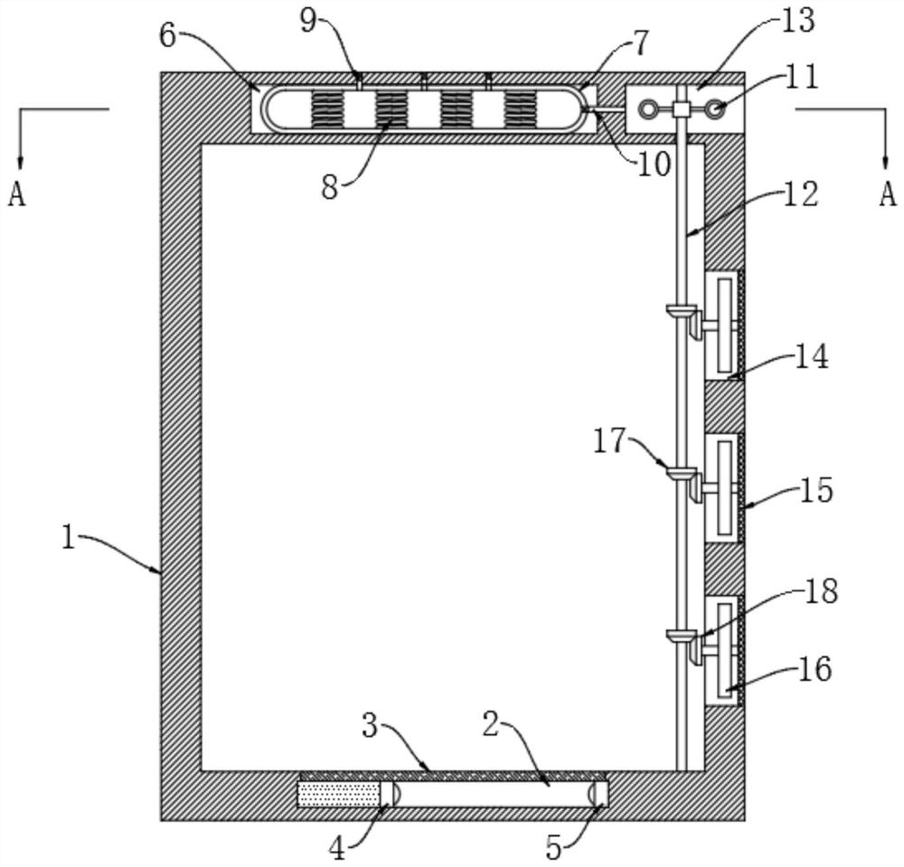
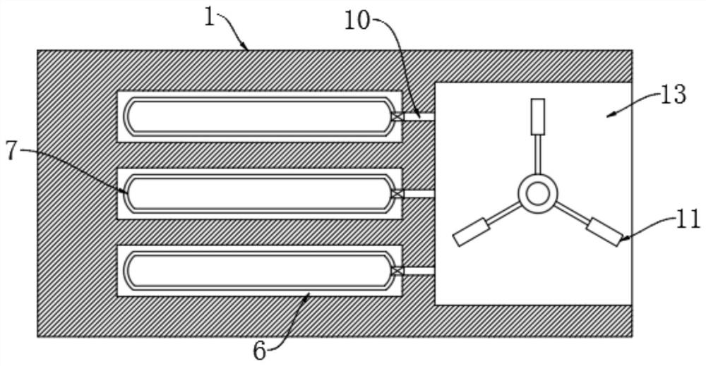
[0016] Refer Figure 1-2 A multi-type power cooling fan is rotated from the cabinet inclu...


PUM


Abstract

The invention discloses a multi-fan self-rotating and heat-dissipating power cabinet, which includes a cabinet body, a sliding chamber is opened in the side wall of the lower end of the cabinet body, a first conductive sheet is sealed and slidably connected to the sliding chamber, and the sliding chamber is sealed and slidably connected. The sealed cavity at the end of the first conductive sheet and the sliding chamber in the chamber is filled with thermal evaporation liquid, and the other end of the sliding chamber is fixedly connected with the second conductive sheet coupled with the circuit in the cabinet. The present invention can use the high temperature in the power cabinet as the driving force by arranging the first conductive sheet, the second conductive sheet, the wind cup, the cooling fan, the driving mechanism and the transmission mechanism, so that the circuit where the spring is located is turned on, and then the spring energizes and vibrates, so that The elastic air bag sprays airflow to the air cup, and the air cup is used as an intermediary to drive each cooling fan to rotate, so as to achieve the purpose of cooling the power cabinet, effectively protect the electrical components in the cabinet, prolong the service life of the electrical components, and effectively prevent Sundries or water stains have entered the cabinet.

Description

Technical field [0001] The present invention relates to the field of power cabinet, particularly to a multi-type cooling fan from a rotational power cabinet. Background technique [0002] Power cabinets is one of the areas a basic power facilities in the most common and most important equipment, its role is installed, the cabinet internal power circuit and power components to install a large number of power components. The internal circuit elements of the power cabinet structure more complex, when distribution cabinet electrical components in the high load operating state, will generate a lot of heat, if not dissipated these heat, it will cause to the electrical components inside the cabinet corrupted, ranging from lead to power supply with electrical cabinet does not work properly, heavy will cause electrical accidents. [0003] Existing power cabinet cooling means are generally opened in the side wall of the heat sinks the power cabinet, through heat sinks for heat dissipation,...

Claims


Application Information

Patent Timeline
Patent Type & Authority Patents(China)
IPC IPC(8): H02B1/56H02B1/30H02B1/28
CPCH02B1/565H02B1/30H02B1/28
Inventor 杨伟夏春辉陈静
Owner 镇江茗驰电气有限公司
Why Eureka
Try Eureka