
Rotating shaft rotating angle limiting and adjusting mechanism

A technology of rotation angle and adjustment mechanism, applied in the direction of mechanical equipment, brake type, etc., can solve the problems of inconvenient adjustment and poor flexibility, and achieve the effect of wide adjustment range, flexible use and convenient use.

Pending Publication Date: 2020-09-01
南京瑞可赋机器人科技有限公司
View PDF0 Cites 2 Cited by
  • Summary
  • Abstract
  • Description
  • Claims
  • Application Information

AI Technical Summary

Problems solved by technology

[0004] When this structure is in use, the position change of the limit nail is generally provided with several limit holes on the preset rotation path (that is, on the circumferential path of the above-mentioned limit block). When a certain position limit is required, Screw the limit screw into the hole at the corresponding position. This structure has poor flexibility and is inconvenient to adjust.

Method used


Image

  • Rotating shaft rotating angle limiting and adjusting mechanism
  • Rotating shaft rotating angle limiting and adjusting mechanism
  • Rotating shaft rotating angle limiting and adjusting mechanism

Examples


Embodiment Construction

[0019] The present invention will be further described below in conjunction with the accompanying drawings.

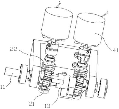
[0020] Such as Figure 1 to Figure 5 , the rotating shaft rotation angle limit adjustment mechanism of the present invention includes a mechanism shaft 11, a stop block 12, a limit block 13, a worm wheel 21 and a worm screw 22, and two worm wheels 21 are installed on the mechanism shaft 11 and between the mechanism shaft 11 The two worms 22 are placed on one side of the mechanism shaft 11 and meshed with the two worm wheels 21 respectively. The two stoppers 12 are respectively fixedly connected to the two worm wheels 21 and rotate together with the worm wheels 21. The limit block 13 is fixedly connected to the mechanism shaft 11 and placed between the two worm gears 21. Two stoppers 13 are provided with two staggered limit arms 131, and the two stoppers 12 are located between the two limiter arms 131 On the path of rotation around the axis of mechanism shaft 11.

[0...


PUM


Abstract

The invention discloses a rotating shaft rotating angle limiting and adjusting mechanism. The rotating shaft rotating angle limiting and adjusting mechanism comprises a mechanism shaft, stop blocks, alimiting block, gears and worms, the two gears are arranged on the mechanism shaft in a penetrating mode and are in clearance fit with the mechanism shaft, the two worms are arranged on one side of the mechanism shaft and are correspondingly engaged with the two gears correspondingly, the two stop blocks are fixedly connected to the two gears correspondingly and rotate along with the gears, the limiting block is fixedly connected to the mechanism shaft and arranged between the two gears, two limiting arms which are arranged in a staggered mode are arranged on the limiting block, and the two stop blocks are located on a rotating path where the two limiting arms rotate around the axis of the mechanism shaft correspondingly. According to the rotating shaft rotating angle limiting and adjusting mechanism, position fixing of the stop blocks is achieved through worm and gear self-locking, the adjusting range is wide, use is flexible, the two stop blocks are arranged, the positions are independent, independent adjustment and control can be achieved, and the mechanism is reliable in operation and convenient to use.

Description

Technical field: [0001] The invention relates to a rotation angle limit adjustment mechanism of a rotation shaft. Background technique: [0002] When the mechanical reciprocating swing structure based on the rotating shaft as the center of rotation is in use, in order to prevent the swinging action from exceeding the limited range during the mechanical execution process, an adjustment mechanism for adjusting the rotation angle of the rotating shaft is often provided in the rotating direction of the rotating shaft. [0003] The existing adjustment structure generally fixes a limit block on the rotating shaft, and then sets two limit nails on the circumferential path of the limit block rotating along the axis of the shaft, and the two limit nails are correspondingly located on the circumferential path of the limit block. When the limit block rotates to the position of the limit nail, it is limited by the limit nail to avoid over-range movement during the reciprocating swing of...

Claims


Application Information

Patent Timeline
Patent Type & Authority Applications(China)
IPC IPC(8): F16D63/00
CPCF16D63/00
Inventor 余永池申陈峰尹建伟
Owner 南京瑞可赋机器人科技有限公司
Learn More