Drainage device for irrigation
A technology of drainage equipment and assembly, which is applied in the direction of mechanical equipment, engines, wind power generation, etc., can solve the problem of single function, and achieve the effect of convenient power output and convenient adjustment
- Summary
- Abstract
- Description
- Claims
- Application Information
AI Technical Summary
Problems solved by technology
Method used
Image

Examples
specific Embodiment approach 1
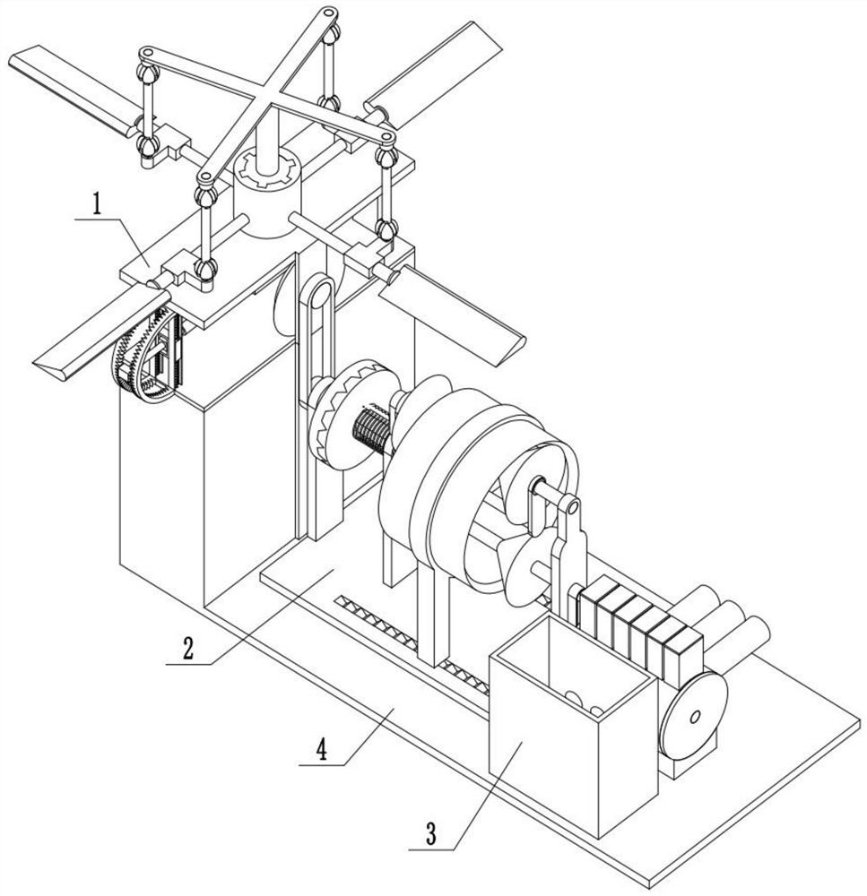
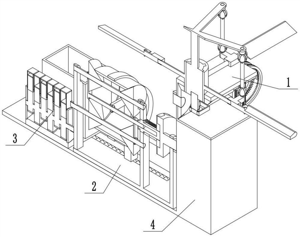
[0029] Combine below Figure 1-13 Description of this embodiment, a drainage device for irrigation, including a power source assembly 1, a transmission assembly 2, a drainage assembly 3, and a connecting frame 4, characterized in that: the power source assembly 1 and the transmission assembly 2 Connection, the transmission assembly 2 is connected with the drainage assembly 3, and the power source assembly 1, the transmission assembly 2, and the drainage assembly 3 are connected with the connecting frame 4.
specific Embodiment approach 2
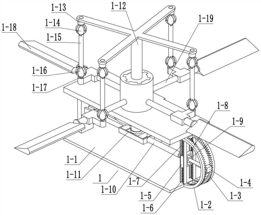
[0031] Combine below Figure 1-13Describe this embodiment, this embodiment will further explain Embodiment 1, the power source assembly 1 includes a power source bottom plate 1-1, an arc plate 1-2, an inner end card slot 1-3, and a manual slide bar 1 -4, middle-end rectangular slider 1-5, middle-end sliding column 1-6, middle-end sliding column push spring 1-7, auxiliary rotor 1-9, middle-end driving rod 1-10, matching rod 1-11, Cross 1-12, curved slider 1-13, spherical rod 1-14, curved slider 2 1-15, spherical rod 2 1-16, curved slider 3 1-17, fan blade 1- 18. Fan blade rotating rod 1-19, inner end clamping rod one 1-20, inner end clamping rod push spring one 1-21, output bevel gear 1-22, output shaft 1-23, transmission bevel gear 1-24, Connecting rod 1-25, arc-shaped plate 1-2 is fixedly connected with power source bottom plate 1-1, inner end card slot 1-3 is arranged on arc-shaped plate 1-2, manual sliding rod 1-4 is connected with arc-shaped plate 1-2 sliding connection,...
specific Embodiment approach 3
[0034] Combine below Figure 1-13 Describe this embodiment, this embodiment will further explain Embodiment 1, the transmission assembly 2 includes a transmission chassis 2-1, a transmission belt A2-2, a clutch lever 2-3, a clutch lever 2 2-4, a clutch Push spring 2-5, prismatic slide bar 2-6, transmission belt B2-7, tapered roller one 2-8, tapered roller two 2-9, transmission shaft one 2-10, transmission sleeve 2-11, Drive sleeve 2-12, transmission shaft 2 2-13, tapered roller 3 2-14, prismatic card slot 2-15, tapered roller 4 2-16, lower prismatic clamping rod 2-17, prismatic card Rod push spring 2-18, mid-end drive slide bar 2-19, clutch lever one 2-3 is rotationally connected with transmission chassis 2-1, transmission belt A2-2 is cooperatively connected with clutch lever one 2-3, clutch lever one 2-3 is connected with the clutch lever two 2-4, the clutch lever two 2-4 is slidingly connected with the prismatic slide bar 2-6, and the clutch push spring 2-5 is socketed and...
PUM
 Abstract
Description
Claims
Application Information
 - Generate Ideas
- Intellectual Property
- Life Sciences
- Materials
- Tech Scout
- Unparalleled Data Quality
- Higher Quality Content
- 60% Fewer Hallucinations
Browse by: Latest US Patents, China's latest patents, Technical Efficacy Thesaurus, Application Domain, Technology Topic, Popular Technical Reports.
© 2025 PatSnap. All rights reserved.Legal|Privacy policy|Modern Slavery Act Transparency Statement|Sitemap|About US| Contact US: help@patsnap.com