


Quick Research
Generate reliable direction feasibility study reports for your R&D in just a few steps.

Technical Q&A
Discover and master advanced knowledge NOW. Basics, ideas, possibilities, all at once.

Find Solutions
As an expert in R&D theories, this can generate solutions to your technical problems instantly.

Evaluate Feasibility
Analyze your overall solution with one click, know your potential R&D risks in advance.

Monitor Landscape
Get weekly tech updates, stay abreast of the latest tech innovations and key insights.
Bevel edge technology of distribution box door panel
A distribution box and door panel technology, which is applied in the field of the bevel edge process of the distribution box door panel, can solve the problems of many punching and punching process steps and decreased production efficiency, and achieves the advantages of improving service life, prolonging service life and improving quality. Effect
- Summary
- Abstract
- Description
- Claims
- Application Information
AI Technical Summary
Problems solved by technology
Method used
Image

Examples
Embodiment 1
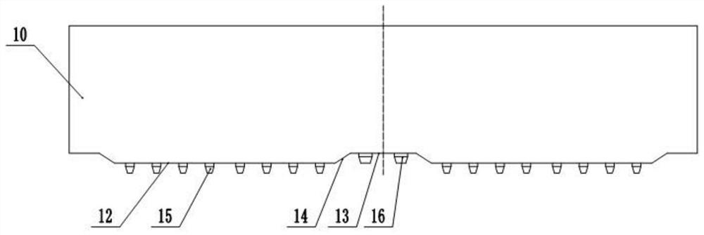
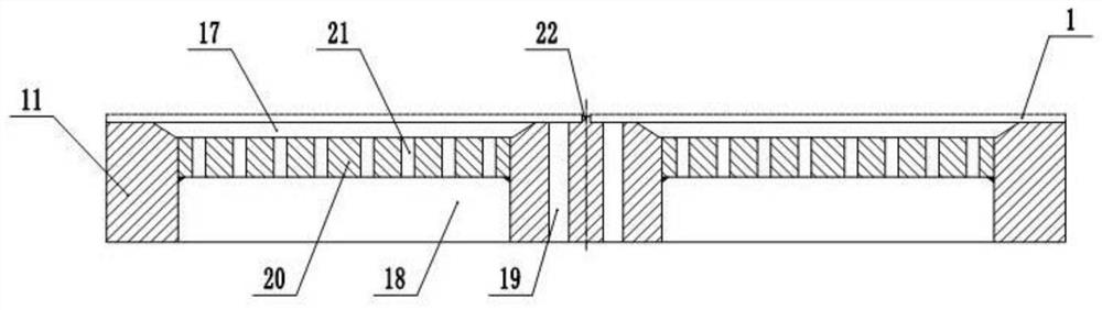
[0037] Example 1 is basically as attached Figure 1 and Figure 2 As shown:
[0038] Distribution box door plate beveled process, the use of beveled special mold, the special mold includes the upper die 10 and the lower die base 11, at the bottom of the upper die 10 is provided with two punch surfaces, the two punch surfaces relative to the centerline of the upper die 10 symmetrical setting, wherein the bump surface includes the raised side 12 and set on both sides of the raised side 12 side 13, the raised edge 12 and the side 13 are set horizontally, the raised edge 12 and the side 13 form a bevel 14, the angle between the bevel 14 and the horizontal plane is not less than 30 °, The angle of the present application is 33 °.
[0039] On the raised edge 12 is fixed a plurality of open punches 15, a plurality of open punches 15 are distributed on the raised edge 12, the open punch 15 is used to flush the heat dissipation hole on the door plate 1, near the upper die 10 centerline of th...
Embodiment 2
[0049] Example 2 is basically as attached Figure 4 As shown:
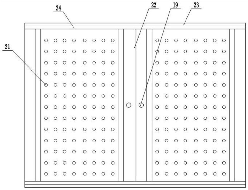
[0050] The difference with Example 1 is that: the load-bearing plate 20 sliding connection in the first housing chamber 18, and the bottom of the first support chamber 18 is fixed with a plurality of support frames 25, adjacent support frames 25 form a gap, and the width of the gap is greater than the aperture of the blanking hole 21, there are multiple elastic pieces fixed between the load-bearing plate 20 and the support frame 25, when the load-bearing plate 20 is not stressed, its top surface exceeds the bottom surface of the die groove 17, in order to prevent the load-bearing plate 20 from shaking, the load-bearing plate 20 is set to a rectangular plate, And on the side of the load-bearing plate 20 fixed a plurality of limit blocks 27, a plurality of limit blocks 27 are distributed on the four sides of the load-bearing plate 20 13, the first holding chamber 18 on the side wall of a plurality of vertical slots 28, lim...
PUM
 Abstract
Description
Claims
Application Information
 - R&D Engineer
- R&D Manager
- IP Professional
- Industry Leading Data Capabilities
- Powerful AI technology
- Patent DNA Extraction
Browse by: Latest US Patents, China's latest patents, Technical Efficacy Thesaurus, Application Domain, Technology Topic, Popular Technical Reports.
© 2024 PatSnap. All rights reserved.Legal|Privacy policy|Modern Slavery Act Transparency Statement|Sitemap|About US| Contact US: help@patsnap.com