
A camera protection device and installation structure for video surveillance for security monitoring

A technology of video monitoring and safety monitoring, which is applied to color TV parts, TV system parts, cleaning methods using tools, etc. It can solve the problems of long-term exposure of the lens, affecting the service life of the equipment, and unsatisfactory protection effects. , to improve the coordination of system actions, facilitate daily cleaning and maintenance, and improve the effect of observation

Inactive Publication Date: 2021-07-27
浙江安防职业技术学院
View PDF7 Cites 0 Cited by
  • Summary
  • Abstract
  • Description
  • Claims
  • Application Information

AI Technical Summary

Problems solved by technology

[0004] Aiming at the deficiencies of the prior art, the present invention provides a camera protection device and installation structure for video surveillance for safety monitoring, which solves the problem that the existing camera protection device has an unsatisfactory protection effect on the camera lens part, and the lens is easily dirty and deposits dust. Long-term exposure to the outside world when the lens is not in use affects the service life of the device

Method used


Image

  • A camera protection device and installation structure for video surveillance for security monitoring
  • A camera protection device and installation structure for video surveillance for security monitoring
  • A camera protection device and installation structure for video surveillance for security monitoring

Examples


Embodiment Construction

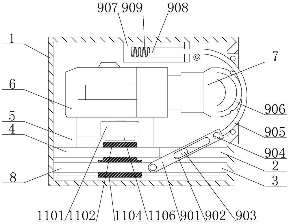
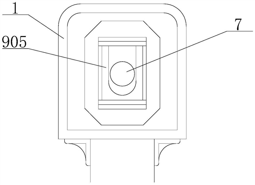
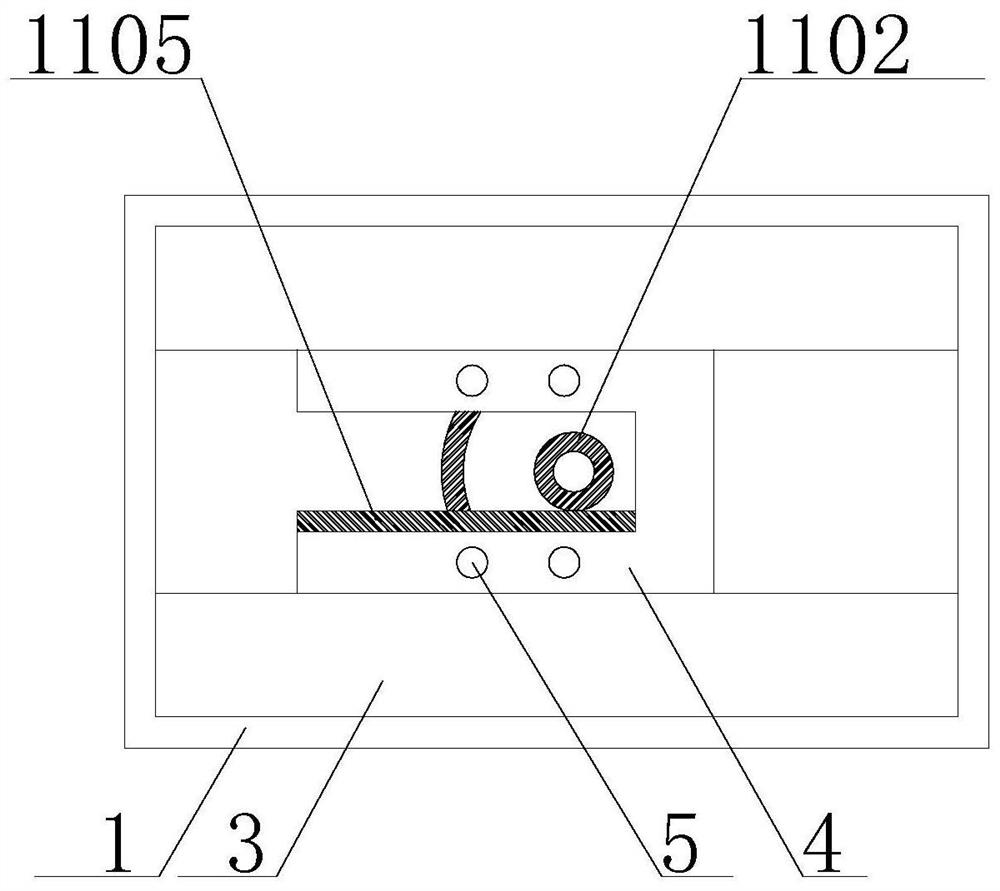
[0028] The technical solutions in the embodiments of the present invention will be clearly and completely described below with reference to the accompanying drawings in the embodiments of the present invention. Obviously, the described embodiments are only a part of the embodiments of the present invention, but not all of the embodiments. Based on the embodiments of the present invention, all other embodiments obtained by those of ordinary skill in the art without creative efforts shall fall within the protection scope of the present invention.

[0029] see Figure 1-6 , a camera protection device and installation structure for video surveillance for safety monitoring, comprising a housing 1, the left and right sides of the inner wall of the housing 1 are provided with a first slide rail 2 and a second slide rail 3, and the first slide rail 2 is arranged on the Above the second slide rail 3, a slide plate 4 is slidably connected in the first slide rail 2, and four support colu...


PUM


Abstract

The invention discloses a camera protection device and installation structure for video monitoring for safety monitoring, which comprises a casing, and a first sliding rail and a second sliding rail are arranged on the left and right sides of the inner wall of the casing. The invention relates to the field of electronic monitoring equipment. The protective device and installation structure of the video monitoring camera for safety monitoring reduce the exposed area of ​​the lens through the cover plate, and at the same time, the lens can enter the casing when not in use through the transmission action between the stepping motor and the first spur gear Inside, it provides good safety protection. The pulling action of the cover plate is realized through the stepping motor and the second flat gear, and three action effects of lens exposure, lens wrapping and lens maintenance are realized, which facilitates the daily cleaning and maintenance of the lens . This solves the problem that the existing camera protection device has an unsatisfactory protective effect on the camera lens part, the lens is easily dirty and deposits dust, and the long-term exposure of the lens to the outside world affects the service life of the equipment when it is not in use.

Description

technical field [0001] The invention relates to the field of electronic monitoring equipment, in particular to a camera protection device and an installation structure for video monitoring for safety monitoring. Background technique [0002] The emergence of surveillance cameras has greatly strengthened the safety of urban public areas. Surveillance cameras can collect image resources in public places, which is conducive to preventing public safety accidents and providing evidence for the investigation of public safety accidents. [0003] The existing patent (publication number: CN110617391A) discloses a camera protection device, including a main splint, an auxiliary splint and a connecting shaft, the main splint and the auxiliary splint are connected by a connecting shaft, and a spring is arranged in the connecting shaft for Apply clamping force. In the process of realizing the present invention, the inventor found that at least the following problems have not been solved ...

Claims


Application Information

Patent Timeline
Patent Type & Authority Patents(China)
IPC IPC(8): F16M11/04F16M11/18H04N5/225B08B1/00B08B17/04
CPCF16M11/04F16M11/045F16M11/18B08B1/00B08B17/04H04N23/50B08B1/143
Inventor 吴贤平
Owner 浙江安防职业技术学院
Learn More