


Quick Research
Generate reliable direction feasibility study reports for your R&D in just a few steps.

Technical Q&A
Discover and master advanced knowledge NOW. Basics, ideas, possibilities, all at once.

Find Solutions
As an expert in R&D theories, this can generate solutions to your technical problems instantly.

Evaluate Feasibility
Analyze your overall solution with one click, know your potential R&D risks in advance.

Monitor Landscape
Get weekly tech updates, stay abreast of the latest tech innovations and key insights.
A positioning device and welding method for butt welding of thin-walled pipes
A positioning device and welding method technology, applied in welding equipment, welding accessories, laser welding equipment, etc., can solve the problems of difficult positioning and high scrap rate of thin-walled pipe welding, so as to improve the overall efficiency of welding, reduce scrap rate and cost , Simple and efficient installation and operation
- Summary
- Abstract
- Description
- Claims
- Application Information
AI Technical Summary
Problems solved by technology
Method used
Image

Examples
Embodiment 1
[0037] A tungsten thin-walled tube has an outer diameter of 14mm, a wall thickness of 0.5mm, and a length of 100mm. Two pieces are butt-welded by electron beam self-fusion. The specific method is as follows:
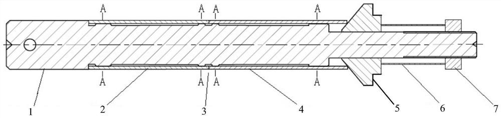
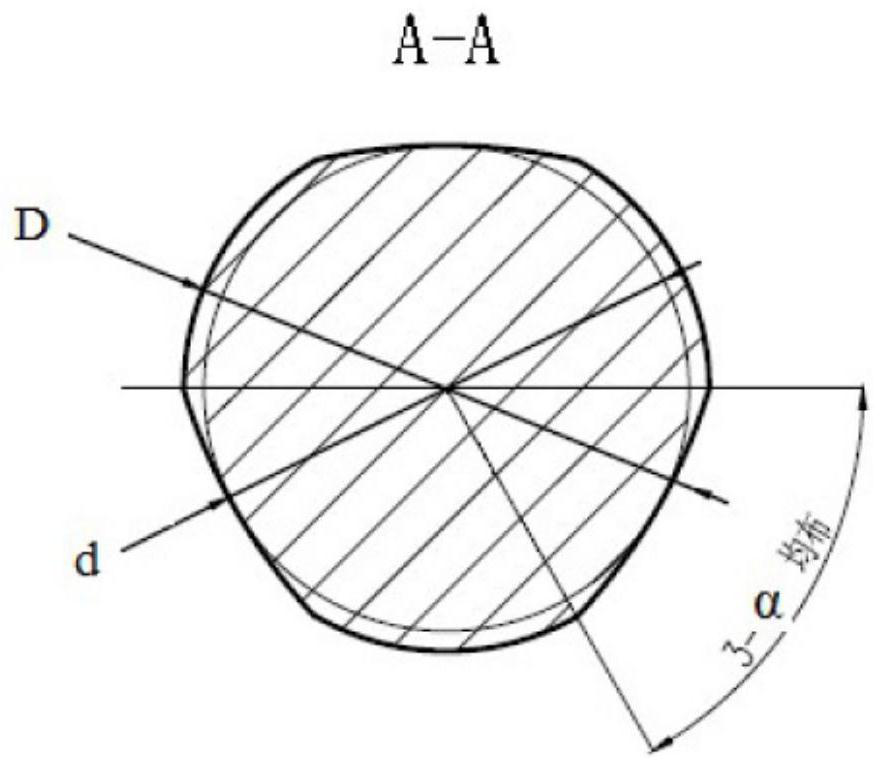
[0038] Positioning device: The positioning device includes a mandrel, a plug, a spring and a fastening nut. One end of the mandrel is the clamping part of the chuck, which is designed as a cylinder with a diameter of 14mm. Four cam structures are designed and processed on the mandrel. The width of the cam structure along the mandrel axis is 5mm. Each cam structure includes three protrusions evenly distributed in the circumferential direction, where α is 90°, the major diameter D is 13 mm, and the minor diameter d is 11 mm. The distance between two adjacent cam structures at the butt weld of the thin-walled pipe is 3mm.
[0039] Installation and welding method: Set two thin-walled tubes on the mandrel in turn to ensure that the end faces are in close contact; install the...
Embodiment 2
[0041] A TZM alloy thin-walled tube has an outer diameter of 20mm, a wall thickness of 1mm, and a length of 80mm. The same three tubes are installed at one time for laser self-fluxing butt welding. The specific method is:
[0042] Positioning device: The positioning device includes a mandrel, a plug, a spring and a fastening nut. One end of the mandrel is the clamping part of the chuck, designed as a cylinder with a diameter of 20mm, and 6 cam structures are designed and processed on the mandrel, and the width of the cam structure along the mandrel axis is 8mm. The cam structure includes three protrusions evenly distributed in the circumferential direction, where α is 100°, the major diameter D is 18 mm, and the minor diameter d is 16 mm. The distance between two cam structures at the butt weld of adjacent thin-walled pipes is 5 mm.
[0043] Installation and welding method: Set three thin-walled tubes on the mandrel in turn to ensure close contact between the end faces; instal...
PUM
| Property | Measurement | Unit |
|---|---|---|
| width | aaaaa | aaaaa |
| thickness | aaaaa | aaaaa |
| diameter | aaaaa | aaaaa |
Abstract
Description
Claims
Application Information
 - R&D Engineer
- R&D Manager
- IP Professional
- Industry Leading Data Capabilities
- Powerful AI technology
- Patent DNA Extraction
Browse by: Latest US Patents, China's latest patents, Technical Efficacy Thesaurus, Application Domain, Technology Topic, Popular Technical Reports.
© 2024 PatSnap. All rights reserved.Legal|Privacy policy|Modern Slavery Act Transparency Statement|Sitemap|About US| Contact US: help@patsnap.com