Workbench for hinge machining

A workbench and hinge technology, which is applied to metal processing equipment, folding plates, perforating tools, etc., can solve the problems of inconvenient adjustment of the punching distance, and achieve fast clamping speed, convenient stamping processing, and simple operation

Inactive Publication Date: 2020-08-28
黄展雄
View PDF0 Cites 6 Cited by
  • Summary
  • Abstract
  • Description
  • Claims
  • Application Information

AI Technical Summary

Problems solved by technology

[0003] During the production and processing of hinges, stamping processing tables are needed. During the stamping process of existing hinge processing stamping equipment, the punching spacing is inconvenient to adjust, and it is difficult to meet people's needs.

Method used


Image

  • Workbench for hinge machining
  • Workbench for hinge machining
  • Workbench for hinge machining

Examples


Embodiment 1

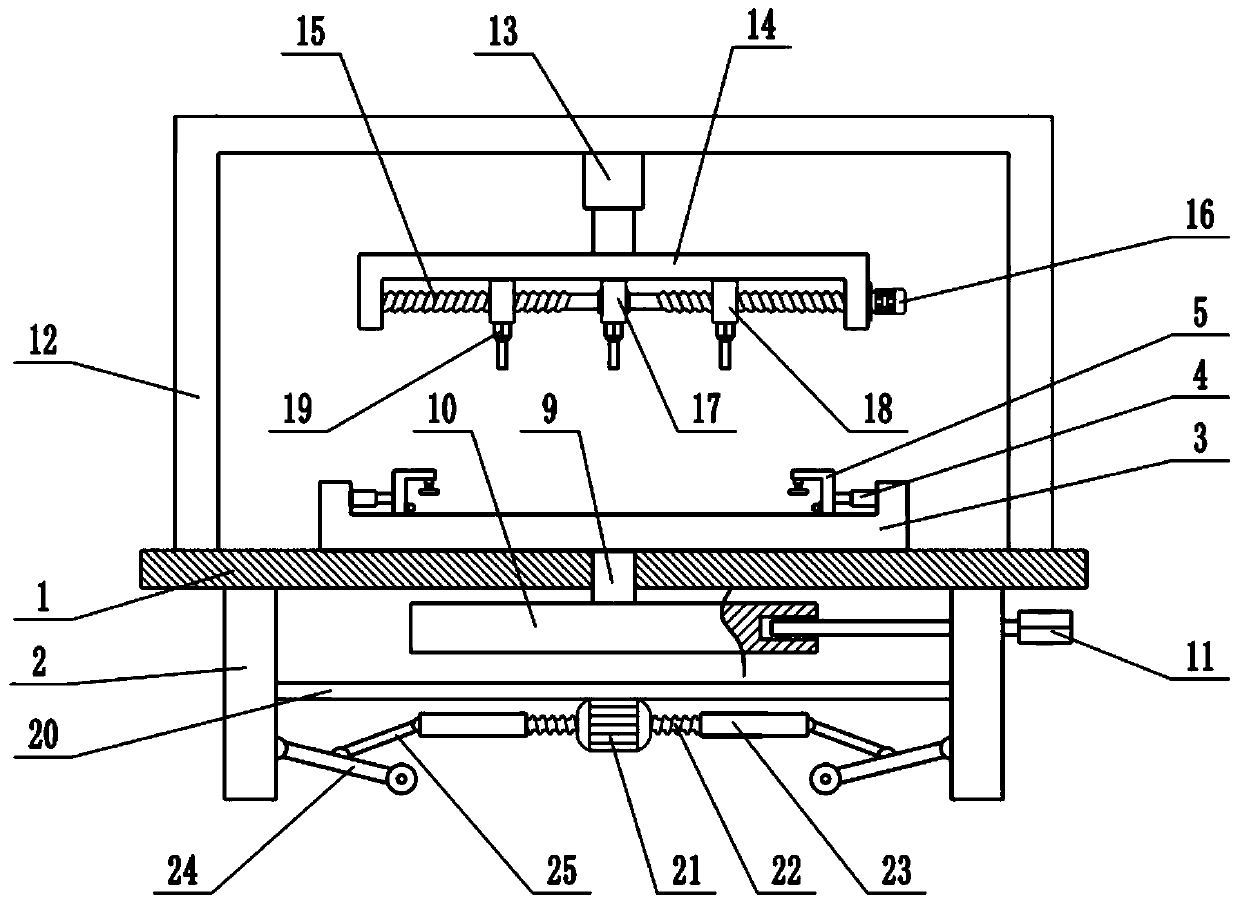
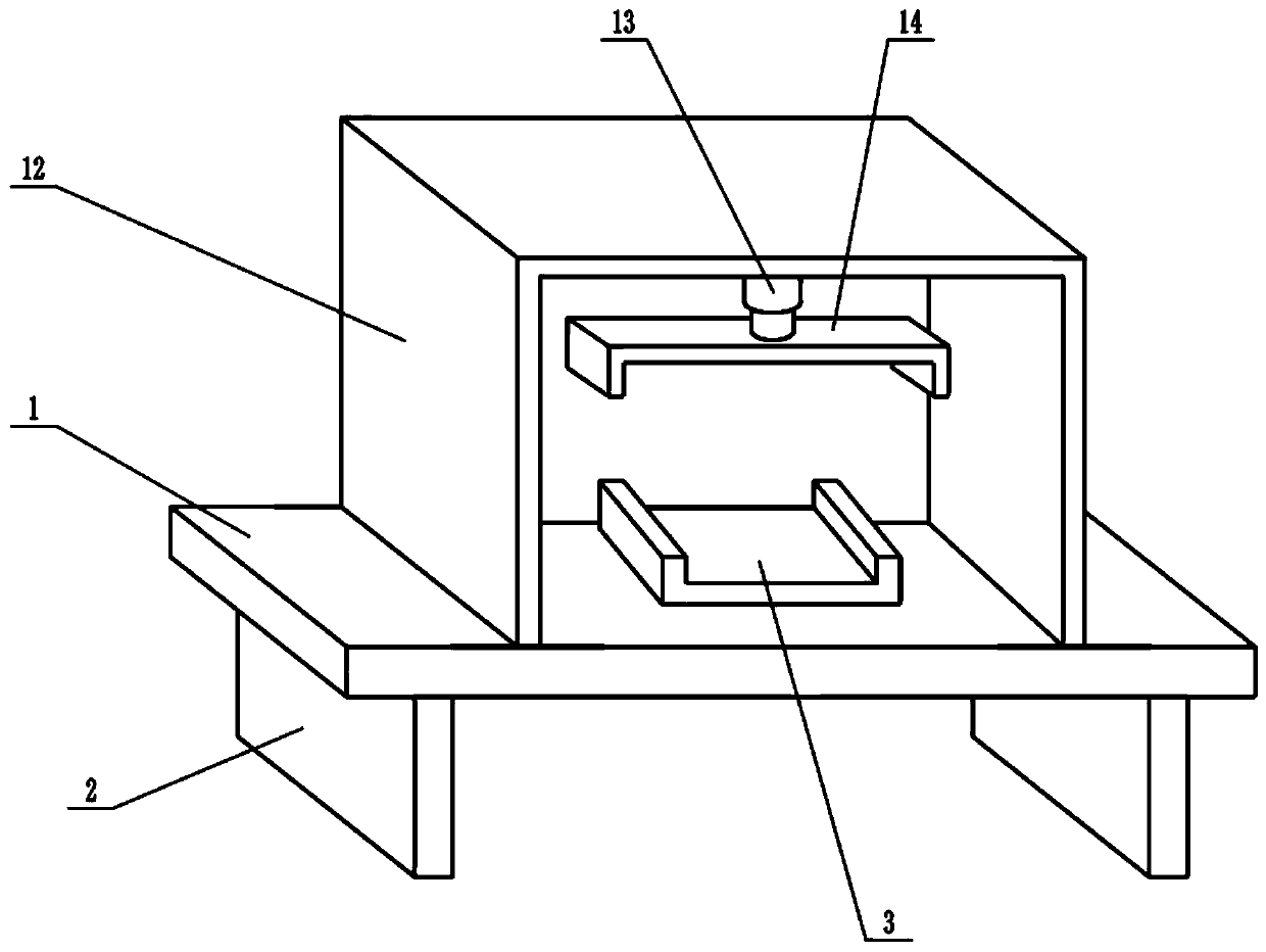
[0022] see Figure 1-3 , In the embodiment of the present invention, a workbench for hinge processing includes a workbench 1, a support plate 2, a rotary table 3, a third telescopic mechanism 13 and a stamping die 19. The bottom of the workbench 1 is fixedly connected with a support Plate 2, a fixing frame 12 is fixedly connected to the upper surface of the worktable 1, a third telescopic mechanism 13 is fixedly connected to the top of the fixing frame 12, the third telescopic mechanism 13 is an electric hydraulic telescopic cylinder, and the lower end of the third telescopic mechanism 13 is fixedly connected There is a lifting frame 14, a bidirectional screw rod 15 is installed inside the lifting frame 14, the left and right ends of the bidirectional screw rod 15 are respectively connected to the side wall of the lifting frame 14 in rotation, and a fixing block 17 is installed inside the lifting frame 14, and the fixing block 17 Located in the middle of the lifting frame 14, ...

Embodiment 2

[0024] On the basis of Embodiment 1, a moving mechanism is installed below the worktable 1, and the moving mechanism includes a mounting plate 20, a biaxial motor 21, a driving screw 22, a sleeve 23, a connecting rod 24 and a movable rod 25. The worktable 1 There is a mounting plate 20 below the mounting plate 20, the end of the mounting plate 20 is fixedly connected with the support plate 2, and the lower surface of the mounting plate 20 is fixedly connected with a biaxial motor 21. The biaxial motor 21 is a forward and reverse rotation motor. The two shaft extension ends are respectively installed with a driving screw 22, the end of the driving screw 22 is sleeved with a sleeve 23, the driving screw 22 is threadedly connected with the sleeve 23, and the end of the sleeve 23 is hinged with a movable rod 25, A connecting rod 24 is hinged on the side wall of the support plate 2, the lower end of the movable rod 25 is hinged with the middle of the connecting rod 24, and a roller ...


PUM


Abstract

The invention relates to the field of machining equipment, in particular to a workbench for hinge machining. The workbench comprises a workbench body, supporting plates, a rotating table, a third telescopic mechanism and stamping dies, wherein the bottom of the workbench is fixedly connected with the supporting plates; the upper surface of the workbench is fixedly connected with a fixing frame; the top of the fixing frame is fixedly connected with the third telescopic mechanism; the lower end of the third telescopic mechanism is fixedly connected with a lifting frame; a bidirectional screw rodis mounted in the lifting frame; fixing blocks are mounted in the lifting frame; the bidirectional screw rod is sleeved with slide blocks; the stamping dies are mounted on the lower surfaces of the fixing blocks and the slide blocks correspondingly; the rotating table is mounted on the upper surface of the workbench; a clamping mechanism is mounted on the rotating table; and a moving mechanism ismounted below the workbench. The clamping mechanism is used for pressing a hinge, so that the hinge can keep stable; high clamping speed is achieved; and operation is easy and very convenient. The distance between the stamping dies can be adjusted by arranging the bidirectional lead screw, so that the machining efficiency is greatly improved.

Description

technical field [0001] The invention relates to the field of mechanical processing equipment, more particularly, to a workbench for hinge processing. Background technique [0002] A hinge is a mechanical device used to connect two solids and allow relative rotation between them. The hinge may be constructed of movable components, or of collapsible material. The hinges are mainly installed on doors and windows. [0003] In the production and processing of hinges, a stamping processing table is required. During the stamping process of the existing hinge processing stamping equipment, it is inconvenient to adjust the spacing of the punching holes, which is difficult to meet people's needs. SUMMARY OF THE INVENTION [0004] The purpose of the present invention is to provide a workbench for hinge processing, so as to solve the problems raised in the above-mentioned background art. [0005] To achieve the above object, the present invention provides the following technical so...

Claims


Application Information

Patent Timeline
IPC IPC(8): B21D28/24B21D28/04B21D28/34B21D28/36B21D53/40
CPCB21D28/04B21D28/24B21D28/34B21D28/36B21D53/40
Inventor 黄展雄
Owner 黄展雄
Why Eureka
Try Eureka