
Duct piece backfilling grouting body core-pulling inspection device and inspection method thereof

A technology of grouting and testing devices behind the wall, which is applied in the direction of sampling devices, material inspection products, and preparation of test samples. The inspection operation is simple and easy to understand, the construction efficiency is high, and the device structure is simple

Pending Publication Date: 2020-08-25
YSD RAIL TRANSIT CONSTR CO LTD +1
View PDF0 Cites 0 Cited by
  • Summary
  • Abstract
  • Description
  • Claims
  • Application Information

AI Technical Summary

Problems solved by technology

One is to judge the grouting effect according to the ground conditions combined with the grouting amount, grouting pressure and other empirical values, and then judge the grouting after the inspection wall according to the seepage leakage point in the tunnel, the posture of the formed segment and the feedback data of the ground monitoring measurement Effect, this method cannot intuitively know the grouting body effect of each part, so it cannot judge in time whether it is necessary to carry out secondary grouting, and it is often known only after a problem occurs, which can easily lead to construction quality and construction accidents
The other is to use radar scanning technology to detect the effect of grouting on the wall of the segment. The disadvantage of this method is that the equipment cost is high, and the radar is prone to failure when working in the harsh environment of humidity and high temperature in tunnel construction, and the misjudgment rate High, cumbersome and complicated operation

Method used


Image

  • Duct piece backfilling grouting body core-pulling inspection device and inspection method thereof

Examples


Embodiment Construction

[0027] The present invention will be further described below in combination with specific embodiments and accompanying drawings.

[0028] A subway shield section project in Guangzhou City, Guangdong Province, the section passes through high-pressure gas pipes, dense building villages, rivers, pedestrian bridges, passenger stations, and high-speed railway stations on the side. There are more than 200 houses and workshops within a width of 60m, some of which are dilapidated, and there is also an ancient well and ancestral hall. This area has high requirements for ground settlement and settlement of heavy structures. If the grouting effect is not ideal, defects such as voids, lack of compactness, and loose layers will easily occur, which will lead to ground subsidence, cracking of the surrounding building structure, and even induce serious disasters such as ground collapse, tunnel collapse, and building collapse. The application of the slurry core-pulling inspection device can ef...


PUM


Abstract

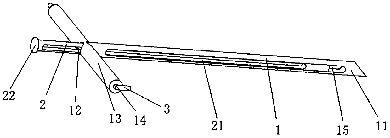
The invention discloses a duct piece backfilling grouting body core-pulling inspection device and an inspection method thereof. The device comprises a drill rod and an ejector rod. The drill rod is ofa hollow structure with openings at two ends, one end is a sharp drill end, the other end is an ejector rod imbedding end, and the ejector rod is inserted into the drill rod from the ejector rod imbedding end and can move back and forth in the drill rod. When the device is adopted for inspection, the steps of duct piece backfilling grouting, drill rod jacking, core sample extraction and core sample jacking are sequentially carried out, and simplicity and convenience are achieved. The device is low in cost and easy and convenient to operate, the quality of the duct piece grouting body can be detected in time, rapidly, easily and effectively, the shield construction quality is effectively guaranteed, and the risks of sedimentation and collapse of ground buildings caused by the quality problem of the grouting body are avoided.

Description

technical field [0001] The invention relates to the technical field of grouting quality inspection in shield tunnel construction, in particular to a core-pulling inspection device and inspection method for grouting body behind a segment wall. Background technique [0002] After the shield tunnel segment is assembled, there is a certain gap between the segment and the soil, and the gap is filled with grouting through the segment wall in time, which can effectively prevent the leakage, settlement and floating of the segment. For example, if the effect of grouting behind the wall is not ideal, defects such as voids, lack of compactness, and loose layers may easily occur, which may lead to ground subsidence, cracks in the surrounding building structure, and even induce serious disasters such as ground collapse, tunnel collapse, and building collapse. The effect of grouting after the film wall is particularly important. [0003] At present, there are two commonly used post-grout...

Claims


Application Information

Patent Timeline
Patent Type & Authority Applications(China)
IPC IPC(8): G01N33/24G01N1/08G01N1/36
CPCG01N1/08G01N1/36G01N33/24
Inventor 朱俊勇宋攀登聂军吴有亮张弦段谦
Owner YSD RAIL TRANSIT CONSTR CO LTD
Learn More