
Backlight imaging device

An imaging device and backlight technology, applied in the direction of using optical devices, measuring devices, transportation and packaging, etc., can solve the problem of placing chips on the light source, etc.

Pending Publication Date: 2020-08-25
BEIJING CITY UNIVERSITY
View PDF0 Cites 3 Cited by
  • Summary
  • Abstract
  • Description
  • Claims
  • Application Information

AI Technical Summary

Problems solved by technology

[0003] The purpose of the present invention is to provide a backlight imaging device to solve the technical problem of placing the chip on the light source when measuring the chip in the prior art to a certain extent

Method used


Image

  • Backlight imaging device

Examples


Embodiment Construction

[0021] In order to make the purpose, technical solutions and advantages of the embodiments of the present application clearer, the technical solutions in the embodiments of the present application will be clearly and completely described below in conjunction with the drawings in the embodiments of the present application. Obviously, the described embodiments are only It is a part of the embodiments of this application, not all of them. The components of the embodiments of the application generally described and illustrated in the figures herein may be arranged and designed in a variety of different configurations. Accordingly, the following detailed description of the embodiments of the application provided in the accompanying drawings is not intended to limit the scope of the claimed application, but merely represents selected embodiments of the application. Based on the embodiments of the present application, all other embodiments obtained by those skilled in the art without...


PUM


Abstract

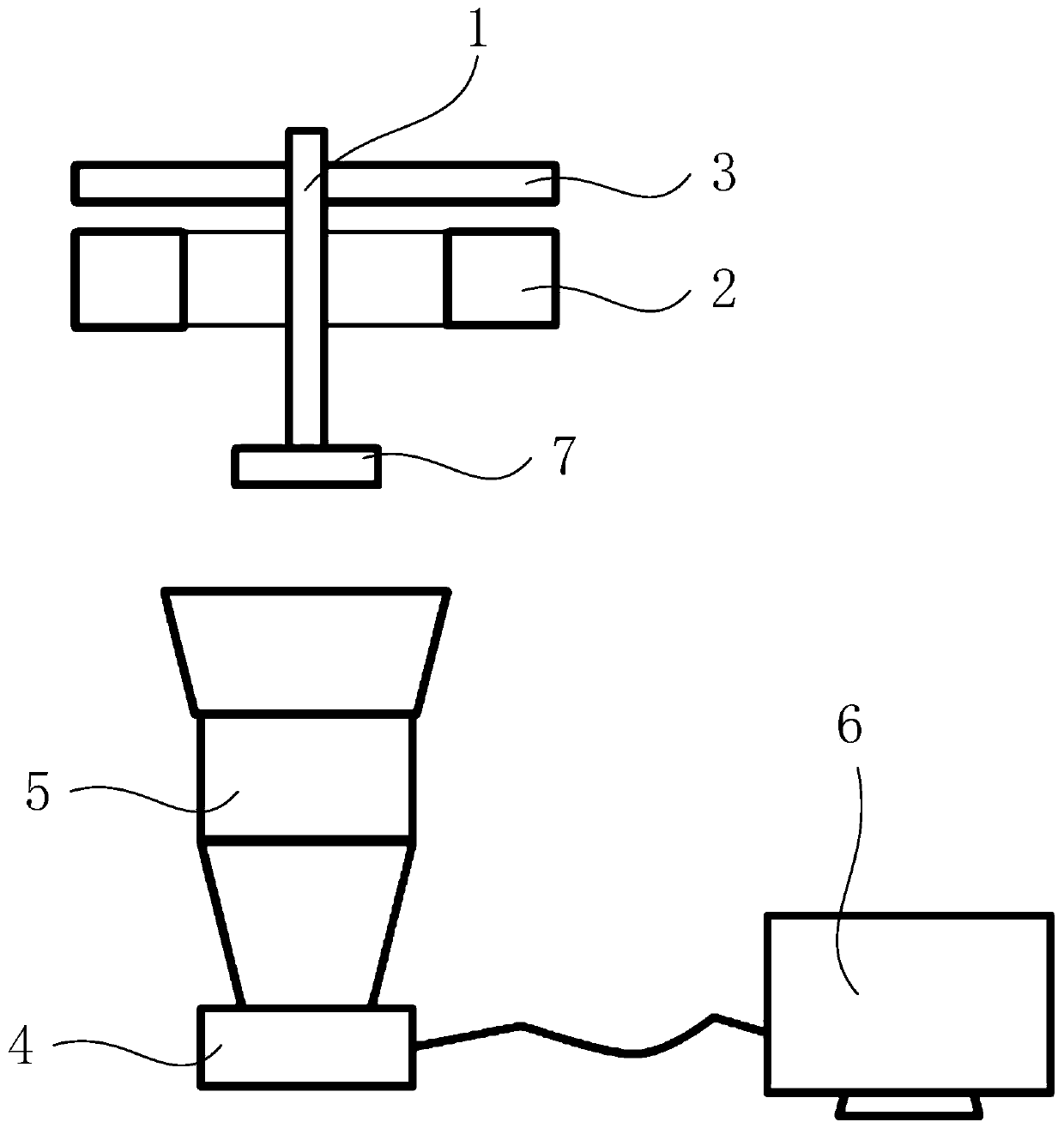
The invention relates to the technical field of chip detection, in particular to a backlight imaging device. The backlight imaging device comprises a manipulator, a light source assembly, a reflectorand an image acquisition device. The manipulator can pick up a chip to be detected and move the chip to a detection position. The image acquisition device is positioned below the detection position and is used for acquiring an image of the chip. The reflector is located above the chip and is fixedly connected with the manipulator. The light source assembly is located between the chip and the reflector, light emitted by the light source assembly irradiates towards the reflector, and the light emitted by the light source assembly cannot directly irradiate the plate face of the side, facing the camera, of the chip. After light rays irradiate the reflector, the light rays are reflected back through the reflector, the reflected light rays vertically and downwards irradiate into the image acquisition device below the reflector, part of the reflected light rays are shielded by the chip, imaging of the chip on the image acquisition device is black, and therefore the backlight imaging effect isachieved.

Description

technical field [0001] The invention relates to the technical field of chip detection, in particular to a backlight imaging device. Background technique [0002] Before tinning the pins of the chip, it is necessary to measure the dimensions of the chip with high precision. At present, backlight imaging is usually used, that is, the chip is placed on the light source, and the light from the light source cannot pass through the chip to form a backlight effect; The chip is photographed, and the obtained image can be processed to obtain the measurement data. However, during the measurement, the chip needs to be picked up by the manipulator and placed on the light source. After the measurement is completed, the chip needs to be picked up again to transfer the chip to the next process. The process of picking and placing the chip causes the relative position of the manipulator and the chip to change. , which in turn leads to the problem of inaccurate positioning in the subsequent ...

Claims


Application Information

Patent Timeline
Patent Type & Authority Applications(China)
IPC IPC(8): G01B11/00B65G47/91
CPCB65G47/91G01B11/00
Inventor 张永忠
Owner BEIJING CITY UNIVERSITY
Learn More