
Novel solar street lamp

A technology of solar street lights and solar panels, applied in the field of solar street lights, can solve the problems of inability to adjust the height of street lights, complicated installation process of solar street lights, and inability to adjust the inclination angle of solar panels, so as to achieve the effect of improving energy storage efficiency

Pending Publication Date: 2020-08-25
SICHUAN DIZHIYUAN NEW ENERGY SCI & TECHCO LTD
View PDF3 Cites 0 Cited by
  • Summary
  • Abstract
  • Description
  • Claims
  • Application Information

AI Technical Summary

Problems solved by technology

[0003] The installation process of existing solar street lamps is complicated, the positions of street lamps and solar panels are relatively fixed, and the height of street lamps cannot be adjusted according to different environments, nor can the inclination angle of solar panels be adjusted, which reduces the cost of solar panels. Utilization of sunlight

Method used


Image

  • Novel solar street lamp
  • Novel solar street lamp
  • Novel solar street lamp

Examples


Embodiment 1

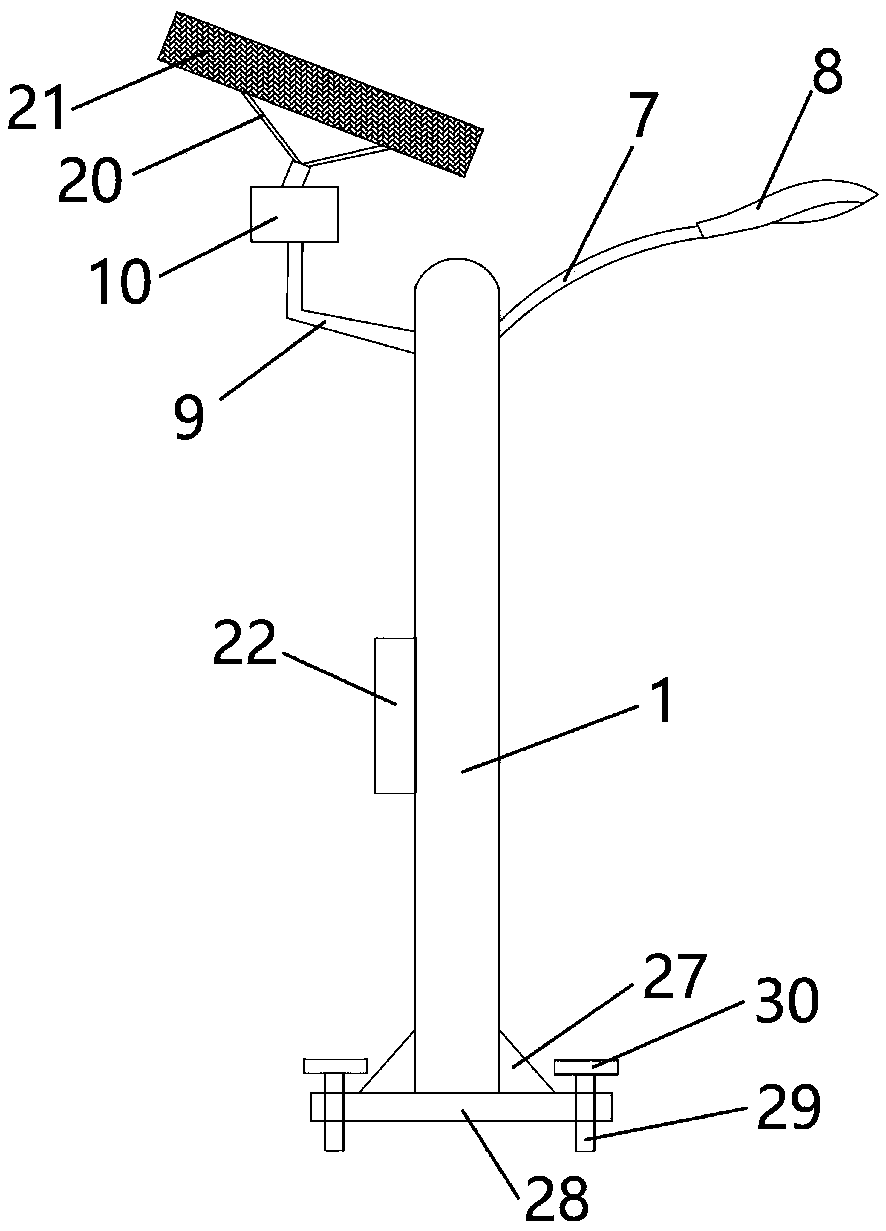
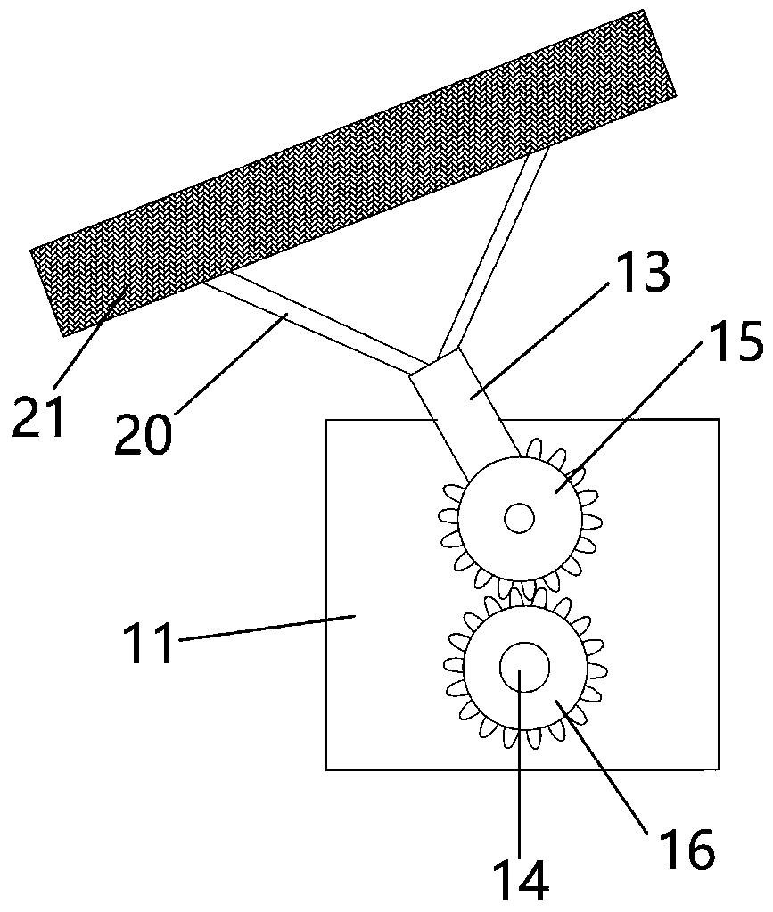
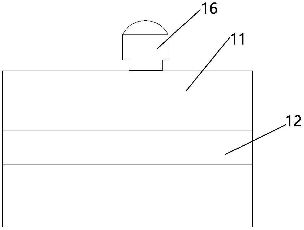
[0024] Such as figure 1 , Figure 4 and Figure 5 As shown, this embodiment provides a new type of solar street lamp 8, which includes a street lamp pole 1, a solar panel 21 and a street lamp 8. A groove 2 is provided in the street lamp pole 1, and grooves 2 are provided on the left and right sides of the groove 2 along the vertical direction. Slide rail 3, electric lifter 5 is installed in the groove 2, the upper end surface of electric lifter 5 is fixedly provided with fixed rod 6, and the left and right sides of fixed rod 6 top are respectively provided with first support arm 7 and second support arm 9, the first The support arm 7 and the second support arm 9 respectively pass through the slide rail 3 on the corresponding side and extend to the outside of the street light pole 1, the top of the first support arm 7 is equipped with a street lamp 8, and the top of the second support arm 9 is connected with the second support arm 9 through the rotation mechanism 10. The two ...

Embodiment 2

[0028] This embodiment provides a new type of solar street lamp 8. Embodiment 2 has the same basic features as Embodiment 1, and has the following distinguishing technical features: Figure 6 As shown, it also includes a first support rod 17 and a second support rod 18, one end of the first support rod 17 is rotatably connected to the first gear 14, and the other end of the first support rod 17 is rotatably connected to the second support rod 18, The other end of the second support rod 18 is rotatably connected to the solar cell panel 21 , and a spring 19 is arranged between the second support rod 18 and the solar cell panel 21 . The setting of the first support rod 17 and the second support rod 18 ensures the stability and safety of the solar cell panel 21 during angular rotation, and the setting of the spring 19 facilitates the rotation of the solar cell panel 21 .

[0029] The present invention realizes adjusting the heights of the street lamp 8 and the solar panel 21 accor...


PUM


Abstract

The invention discloses a novel solar street lamp. The street lamp comprises a street lamp pole, solar panels and street lamps. A groove is formed in the street lamp pole; and sliding rails are arranged on the left side and the right side of the groove in the vertical direction. An electric lifter is mounted in the groove; a fixed rod is fixedly arranged on the upper end surface of the electric lifter; and a first supporting arm and a second supporting arm are arranged on the left and right sides of the top of the fixed rod. The first supporting arm and the second supporting arm penetrate through the sliding rails on the corresponding sides respectively and extend out of the street lamp pole, a street lamp is installed at the top of the first supporting arm, the top of the second supporting arm is connected with a connecting rod through a rotating mechanism, the connecting rod is connected with a solar cell panel, and the rotating mechanism can adjust the angle of the solar cell panel.The height of the street lamp and the height of the solar cell panel are adjusted according to different use environments and requirements, the illumination range of the street lamp is wider, and meanwhile the direction of the solar cell panel can be adjusted in an all-around mode according to the sunlight direction.

Description

technical field [0001] The invention relates to the technical field of solar street lamps, in particular to a solar street lamp with high-efficiency energy storage and can be adjusted up and down. Background technique [0002] Solar energy is an inexhaustible, clean, pollution-free and renewable green energy source. Using solar energy to generate electricity has advantages that other conventional energy sources do not have, such as unparalleled cleanliness, high safety, relative breadth and sufficiency of energy, long life, and maintenance-free. Photovoltaic energy is considered to be the twenty-first The most important new energy of the century. Solar street lights use sunlight as energy, use solar panels to charge the battery during the day, and use the battery to supply power to the light source at night, without complicated and expensive pipeline laying, easy installation and maintenance, the layout of the lamps can be adjusted arbitrarily, and the work is stable withou...

Claims


Application Information

Patent Timeline
Patent Type & Authority Applications(China)
IPC IPC(8): F21S9/03F21V23/00F21V21/14F21V21/15F21V21/36F21W131/103
CPCF21S9/035F21V23/003F21V21/14F21V21/15F21V21/36F21W2131/103Y02B20/72
Inventor 李成军
Owner SICHUAN DIZHIYUAN NEW ENERGY SCI & TECHCO LTD
Learn More