Ball valve for floor cleaning robot
A ground cleaning and robot technology, applied in cleaning equipment, household cleaning devices, applications, etc., can solve the problems of untimely opening and closing, achieve the effect of simple structure, change the cleaning method, and improve the cleaning efficiency
- Summary
- Abstract
- Description
- Claims
- Application Information
AI Technical Summary
Problems solved by technology
Method used
Image
Examples
specific Embodiment approach 1
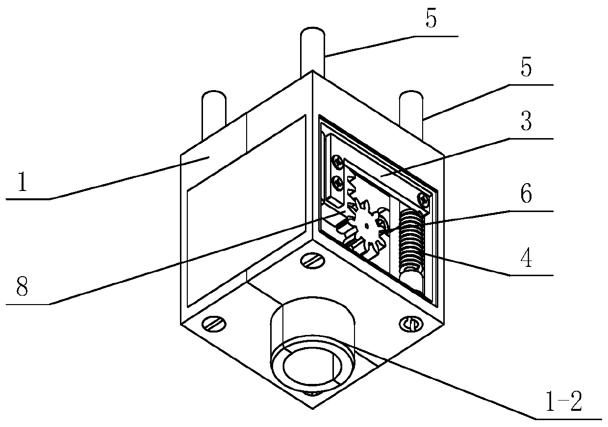
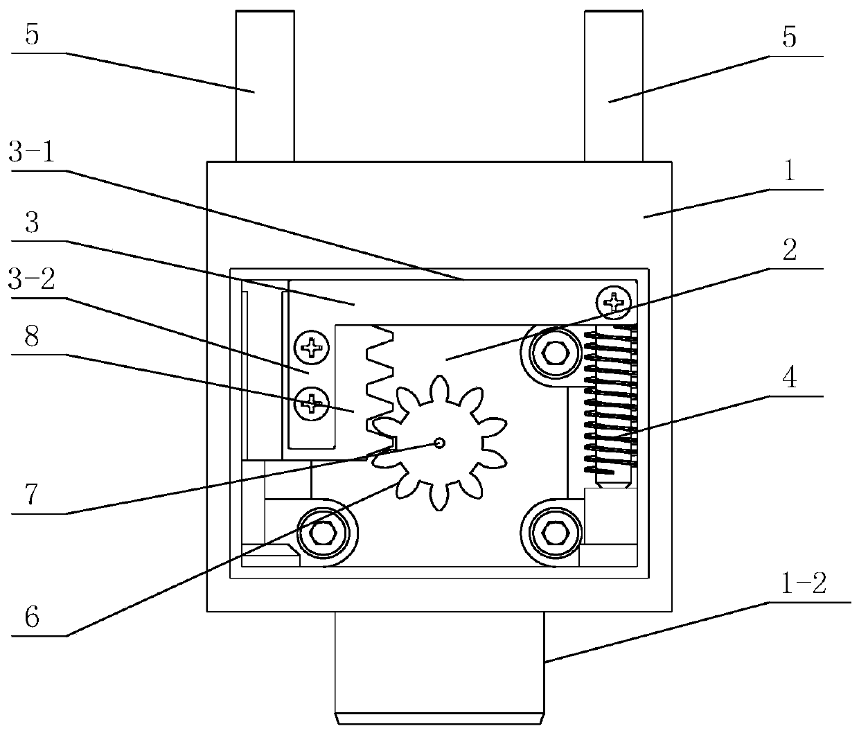
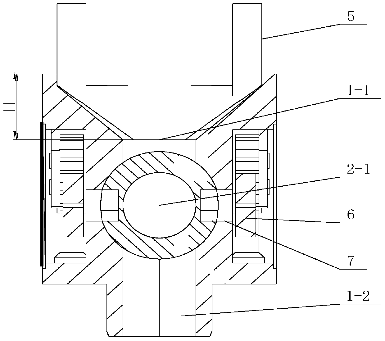
[0013] Specific embodiment one: combination Figure 1 to Figure 3 To explain this embodiment, the ball valve for floor cleaning robot described in this embodiment includes a valve body 1, a valve core 2 and two driving mechanisms. The upper surface of the valve body 1 is provided with a first tuyere 1-1. The lower surface is provided with a second tuyere 1-2, the valve core 2 is provided with a through hole 2-1 penetrating the valve core 2, and the two driving mechanisms are symmetrically installed on both sides of the valve core 2.
[0014] Both of the two driving mechanisms can drive the valve core 2 to rotate, so that the first tuyere 1-1, the through hole 2-1, and the second tuyere 1-2 are connected to form an air duct.
specific Embodiment approach 2
[0015] Specific implementation manner two: combination Figure 1 to Figure 3 To explain this embodiment, each of the driving mechanisms of the ball valve for a floor cleaning robot in this embodiment includes a connecting rod 3, a rotating assembly, a return spring 4, and two driving rods 5. The two rotating assemblies are installed symmetrically On both sides of the valve core 2, two driving rods 5 are vertically arranged side by side. The lower end of each driving rod 5 passes through the upper surface of the valve body 1 and is connected to the rotating assembly. The connecting rod 3 is formed by a cross rod 3-1 The L-shaped rod body composed of the vertical rod 3-2, one end of the horizontal rod 3-1 is connected with the upper end of the vertical rod 3-2 into one body, and the other end of the horizontal rod 3-1 is fixedly connected with the lower part of a driving rod 5. The rod 3-2 is fixedly installed on the side wall of the lower part of the other driving rod 5. The ret...
specific Embodiment approach 3
[0016] Specific implementation mode three: combination Figure 1 to Figure 3 To explain this embodiment, the rotating assembly of a ball valve for a floor cleaning robot described in this embodiment includes a gear 6, a gear shaft 7, and a rack 8. The gear 6 is fixedly connected to the side surface of the valve core 2 through the gear shaft 7, and the rack 8 Vertically fixedly mounted on the vertical rod 3-2, the rack 8 meshes with the gear 6. The other composition and connection relationship are the same as in the second embodiment.
PUM
 Abstract
Description
Claims
Application Information
 - Generate Ideas
- Intellectual Property
- Life Sciences
- Materials
- Tech Scout
- Unparalleled Data Quality
- Higher Quality Content
- 60% Fewer Hallucinations
Browse by: Latest US Patents, China's latest patents, Technical Efficacy Thesaurus, Application Domain, Technology Topic, Popular Technical Reports.
© 2025 PatSnap. All rights reserved.Legal|Privacy policy|Modern Slavery Act Transparency Statement|Sitemap|About US| Contact US: help@patsnap.com


