
Cable winding device for power distribution engineering

A winding device and cable technology, which is applied in the direction of transportation and packaging, thin material handling, and delivery of filamentous materials, etc. It can solve the problems of tight fit of the winding device, time-consuming and labor-intensive cables, and heavy weight of the cables.

Active Publication Date: 2020-08-25
浙江康沃电力有限公司
View PDF9 Cites 4 Cited by
  • Summary
  • Abstract
  • Description
  • Claims
  • Application Information

AI Technical Summary

Problems solved by technology

The existing recycling method usually winds the cable through the winding device, and then removes the wound cable from the winding device for easy storage and recycling. However, the weight of the cable after winding is relatively heavy and the winding device is attached The tight fit makes it time-consuming and labor-intensive for people to remove the reeled cable, which is not conducive to people's use

Method used


Image

  • Cable winding device for power distribution engineering
  • Cable winding device for power distribution engineering
  • Cable winding device for power distribution engineering

Examples


Embodiment Construction

[0029] The present invention will be described in further detail below in conjunction with the accompanying drawings.

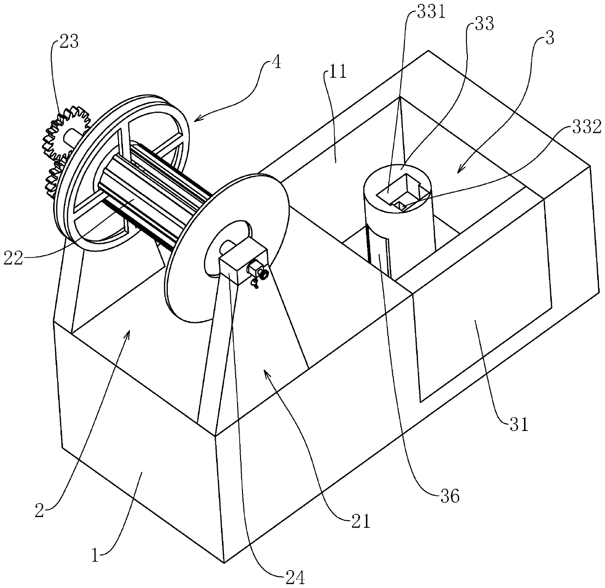
[0030] This embodiment discloses a cable winding device for power distribution engineering, such as figure 1 As shown, the base 1 is included, and the upper end of the base 1 is provided with a winding mechanism 2 and a dismounting mechanism 3. The winding assembly includes a support frame 21 fixed on the base 1, and the support frame 21 is rotatably connected with a winding shaft 22. A drive assembly 23 is installed on the side, and a material shifting mechanism 4 is installed on the winding shaft 22 .

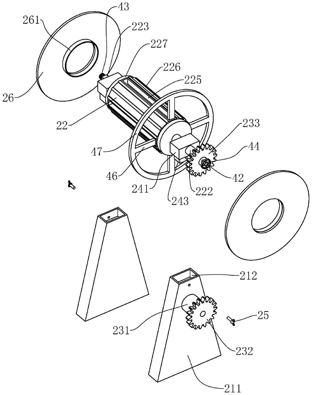
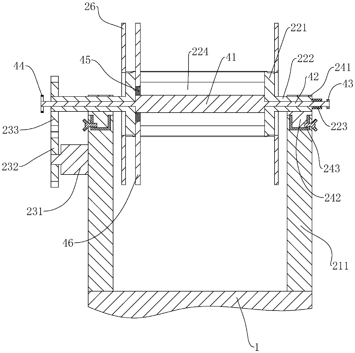
[0031] Such as figure 2 , image 3 As shown, the winding shaft 22 includes a central shaft 221, the two ends of the central shaft 221 are fixed with a rotating shaft 222, and the rotating shaft 222 is connected with a mounting block 24 for rotation, and the two ends of the central shaft 221 are larger than the mounting block 24. The support frame 21 incl...


PUM


Abstract

The invention discloses a cable winding device for power distribution engineering. According to the technical scheme, the cable winding device is characterized by comprising a base, wherein a windingmechanism and a dismounting mechanism are arranged at the upper end of the base; the winding mechanism comprises a supporting frame fixed to the base; the supporting frame comprises two supporting plates; the upper ends of the supporting plates are detachably connected with mounting blocks; a winding shaft is rotationally connected between the two mounting blocks; a material moving mechanism is arranged on the winding shaft; a driving assembly for driving the winding shaft to rotate is arranged on one side of the supporting plates; the winding shaft comprises a center shaft, rotating shafts are fixed to the left end and the right end of the center shaft, and baffles are detachably connected to the left end and the right end of the center shaft; the material moving mechanism comprises fourmoving plates in sliding connection with the center shaft; a dismounting groove is formed in one side of the base; the dismounting mechanism comprises a dismounting column fixed in the dismounting groove; a first embedding groove capable of being matched with the mounting blocks is formed in the upper end of the dismounting column; a dismounting assembly is arranged at the lower end of the first embedding groove; and the dismounting assembly can drive the moving plates to slide. The cable winding device has the functions that a wound cable is easy to take down, and people can conveniently recycle the cable.

Description

technical field [0001] The invention relates to a wire winding device, more specifically it relates to a cable winding device for power distribution engineering. Background technique [0002] Cables and wires are indispensable materials in power distribution projects. In power distribution projects, some old facilities need to recycle the original cables and then rewire them. The existing recycling method usually winds the cable through the winding device, and then removes the wound cable from the winding device for easy storage and recycling. However, the weight of the cable after winding is relatively heavy and the winding device is attached Closer, makes it time-consuming and laborious for people to take off the cable after winding, which is unfavorable for people to use. Contents of the invention [0003] Aiming at the deficiencies in the prior art, the present invention provides a cable winding device for power distribution engineering, which has the function of bein...

Claims


Application Information

Patent Timeline
IPC IPC(8): B65H54/553B65H54/44B65H54/70B65H67/04
CPCB65H54/553B65H54/44B65H54/70B65H67/0411B65H2701/34B65H2301/417
Inventor 蔡佐超廖蓉蓉
Owner 浙江康沃电力有限公司
Learn More