
An intelligent injection mold

An injection mold and mold cavity technology, applied in the field of injection mold structure improvement, can solve problems such as affecting production efficiency, time-consuming, complicated installation and disassembly process, etc. Effect

Active Publication Date: 2021-03-02
SHENZHEN RUIHUA XINXING DIGITAL TECH
View PDF4 Cites 0 Cited by
  • Summary
  • Abstract
  • Description
  • Claims
  • Application Information

AI Technical Summary

Problems solved by technology

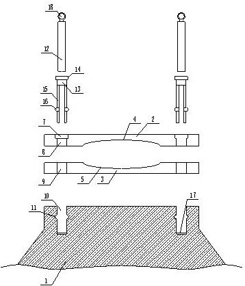
[0002] Injection molds are commonly used tools in parts production. Injection molds are generally fixedly installed on the workbench, but the existing installation method is to use the bolt structure to fix the lower mold of the injection mold on the workbench, and connect the upper mold with the workbench. The lower mold is docked and then fixedly connected together; therefore, it is necessary to use multiple screws to fix the lower mold on the workbench during installation, and then fit the upper mold and the lower mold together and use screws for fixed connection; because Injection molds are often replaced according to production needs or daily wear and tear, and the method of bolt fixing is not only cumbersome to install and disassemble, but also takes a long time, seriously affecting production efficiency

Method used


Image

  • An intelligent injection mold
  • An intelligent injection mold
  • An intelligent injection mold

Examples


Embodiment Construction

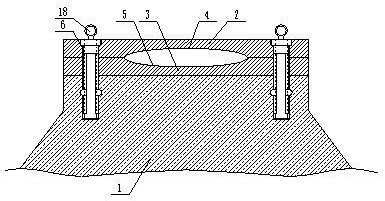
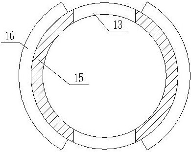
[0025] The present invention is specifically described below in conjunction with accompanying drawing, as Figure 1-5 As shown, the inventive point of the present application is that the upper mold is provided with a plurality of through holes-6, the through holes communicate with the upper and lower surfaces of the upper mold, and the plurality of through holes-the center line of the upper mold is equiangular distribution On the upper die, the through hole one is formed by connecting a thick cylindrical hole 7 and a thin cylindrical hole 8, and the center line of the thick cylindrical hole and the center line of the thin cylindrical hole are in a line On a vertical line, the thick cylindrical hole communicates with the upper surface of the upper die, and the thin cylindrical hole communicates with the lower surface of the upper die;

[0026] The inventive point of the present application is also that the lower mold is provided with a plurality of through holes 9, and the thro...


PUM


Abstract

The invention discloses a novel intelligent injection mold, comprising a workbench, an upper mold and a lower mold, the lower surface of the upper mold is provided with an upper mold cavity, the upper surface of the lower mold is provided with a lower mold cavity, the The upper mold cavity matches the lower mold cavity, and the upper mold is provided with a plurality of through holes, the through holes communicate with the upper and lower surfaces of the upper mold, and the through holes are equiangular with the vertical midline of the upper mold as the center. Distributed on the upper mold, the first through hole is formed by connecting a thick cylindrical hole and a thin cylindrical hole, and the center line of the thick cylindrical hole and the center line of the thin cylindrical hole are in a vertical line. On a straight line, the thick cylindrical hole communicates with the upper surface of the upper die, and the thin cylindrical hole communicates with the lower surface of the upper die. The beneficial effect of the invention is that the assembling process is simple and fast, and the working efficiency is effectively improved.

Description

technical field [0001] The invention relates to the field of structural improvement of injection molds, in particular to an intelligent injection mold. Background technique [0002] Injection molds are commonly used tools in parts production. Injection molds are generally fixedly installed on the workbench, but the existing installation method is to use the bolt structure to fix the lower mold of the injection mold on the workbench, and connect the upper mold with the workbench. The lower mold is docked and then fixedly connected together; therefore, it is necessary to use multiple screws to fix the lower mold on the workbench during installation, and then fit the upper mold and the lower mold together and use screws for fixed connection; because Injection molds are often replaced according to production needs or daily wear and tear, and the method of bolting is not only cumbersome to install and disassemble, but also takes a long time, which seriously affects production eff...

Claims


Application Information

Patent Timeline
Patent Type & Authority Patents(China)
IPC IPC(8): B29C45/17B29C45/26
CPCB29C45/1742B29C45/2602
Inventor 黄景温
Owner SHENZHEN RUIHUA XINXING DIGITAL TECH
Learn More