
Automatic feeding assembly system for engine crankshaft and process method

An automatic on-line and assembly system technology, applied to assembly machines, manufacturing tools, metal processing equipment, etc., can solve problems such as low operating efficiency, low automation level, and crankshaft bumping, so as to improve operating efficiency, improve utilization rate, and reduce area Effect

Active Publication Date: 2020-08-25
DONGFENG MOTOR CORP HUBEI
View PDF6 Cites 2 Cited by
  • Summary
  • Abstract
  • Description
  • Claims
  • Application Information

AI Technical Summary

Problems solved by technology

During the engine assembly process, the crankshaft of the engine has a complex shape and the weight of the parts is heavy. In order to reduce the labor intensity of the operator, a mechanical assist arm or a special spreader is usually used for installation. However, due to the high technical requirements and machining accuracy of the crankshaft, the spreader is used Crankshaft collision and parts damage occur in manual installation
At the same time, the engine bearing shell needs to be installed before the crankshaft is installed. Since the engine bearing shell needs to input the information of the main shaft hole of the cylinder block and the main journal of the crankshaft at the same time, and then match it according to the matching rules, the traditional installation method needs to establish a crankshaft conveying roller outside the assembly line. After inputting the cylinder block and crankshaft information in sequence, the crankshaft is installed, resulting in the disadvantages of low automation level and low operating efficiency during production.

Method used


Image

  • Automatic feeding assembly system for engine crankshaft and process method
  • Automatic feeding assembly system for engine crankshaft and process method

Examples


Embodiment Construction

[0030] The present invention will be further described in detail below in conjunction with the accompanying drawings and specific embodiments.

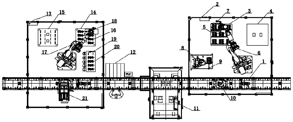
[0031] like figure 1 The engine crankshaft automatic on-line assembly system shown in -2 includes an engine assembly line body 1 and an engine tray 10 arranged on the engine assembly line body 1, along the conveying direction of the engine assembly line body 1, cylinder blocks for the engine cylinder block 5 on the line are sequentially arranged The on-line workstation, the main bearing back-loosening workstation for loosening the main bearing support bolts, the main bearing bush installation station for the main bearing bush installation, and the crankshaft on-line workstation for the crankshaft 16 of the online engine.

[0032] The online workstation on the cylinder block includes the online robot 6 on the cylinder block and the on-line vision system 7 on the cylinder block that can take pictures of the engine block 5; Cylinder blo...


PUM


Abstract

The invention discloses an automatic feeding assembly system for an engine crankshaft and a process method. The automatic feeding assembly system for the engine crankshaft comprises an engine assemblyline body and an engine tray arranged on the engine assembly line body. A cylinder body feeding workstation used for feeding an engine cylinder body, a main bearing loosening workstation used for loosening main bearing support bolts, a main bearing bush installation workstation used for main bearing bush installation and a crankshaft feeding workstation used for feeding an engine crankshaft are sequentially arranged in the conveying direction of the engine assembly line body. Two sets of feeding robots and visual systems are used for achieving automatic assembly of the crankshaft and the cylinder body, the manual carrying operation is omitted, the operation efficiency is obviously improved, the operation speed is adjustable, and the automatic assembling machine can adapt to rapid tightening.

Description

technical field [0001] The invention relates to the technical field of engine assembly, in particular to an engine crankshaft automatic on-line assembly system and a process method. Background technique [0002] The engine crankshaft is one of the most important parts of the engine. The chemical energy released by the combustion of fuel in the engine combustion chamber is transmitted to the crankshaft through the piston connecting rod, and the crankshaft rotates to drive other accessories of the engine to work. During the engine assembly process, the crankshaft of the engine has a complex shape and the weight of the parts is heavy. In order to reduce the labor intensity of the operator, a mechanical assist arm or a special spreader is usually used for installation. However, due to the high technical requirements and machining accuracy of the crankshaft, the spreader is used Manual installation may cause bumps on the crankshaft and damage to parts. At the same time, the engi...

Claims


Application Information

Patent Timeline
IPC IPC(8): B23P21/00
CPCB23P21/004
Inventor 董璠王奔柳佳琛吕方奎王少枫
Owner DONGFENG MOTOR CORP HUBEI
Learn More